Posts Tagged 'Feature extraction'

C# How to: Fuzzy Blur Filter

Article Purpose

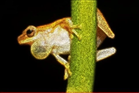
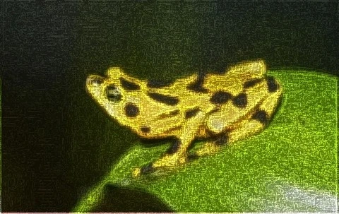
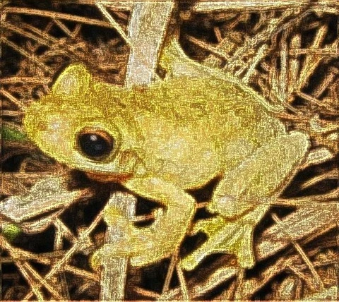
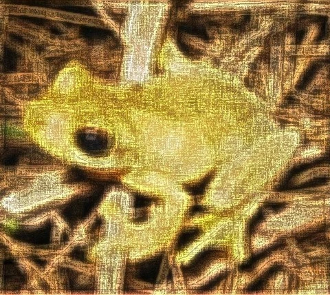
This article serves to illustrate the concepts involved in implementing a Fuzzy Blur Filter. This filter results in rendering  non-photo realistic images which express a certain artistic effect.

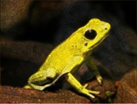
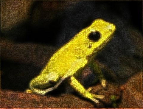
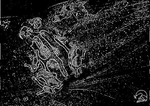
Frog: Filter Size 19×19

Frog: Filter Size 19x19

Sample Source Code

This article is accompanied by a sample source code Visual Studio project which is available for download here.

Using the Sample Application

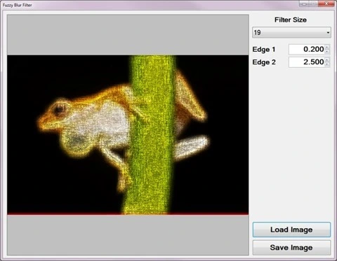
The sample source code accompanying this article includes a based test application. The concepts explored throughout this article can be replicated/tested using the sample application.

When executing the sample application the user interface exposes a number of configurable options:

  • Loading and Saving Images – Users are able to load source/input from the local system by clicking the Load Image button. Clicking the Save Image button allow users to save filter result .
  • Filter Size – The specified filter size affects the filter intensity. Smaller filter sizes result in less blurry being rendered, whereas larger filter sizes result in more blurry being rendered.
  • Edge Factors – The contrast of fuzzy expressed in resulting depend on the specified edge factor values. Values less than one result in detected being darkened and values greater than one result in detected image edges being lightened.

The following image is a screenshot of the Fuzzy Blur Filter sample application in action:

Fuzzy Blur Filter Sample Application

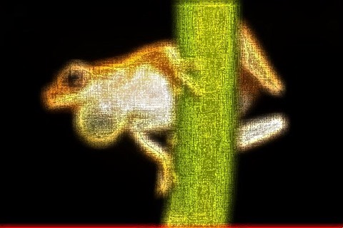
Frog: Filter Size 9×9

Frog: Filter Size 9x9

Fuzzy Blur Overview

The Fuzzy Blur Filter relies on the interference of when performing in order to create a fuzzy effect. In addition results from performing a .

The steps involved in performing a Fuzzy Blur Filter can be described as follows:

  1. Edge Detection and Enhancement – Using the first edge factor specified enhance by performing Boolean Edge detection. Being sensitive to , a fair amount of detected will actually be in addition to actual .
  2. Mean Filter Blur – Using the edge enhanced created in the previous step perform a blur. The enhanced edges will be blurred since a does not have edge preservation properties. The size of the implemented depends on a user specified value.
  3. Edge Detection and Enhancement –  Using the blurred created in the previous step once again perform Boolean Edge detection, enhancing detected edges according to the second edge factor specified.

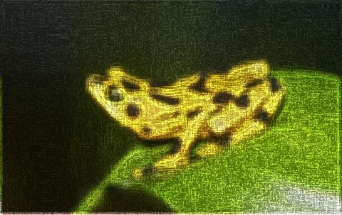
Frog: Filter Size 9×9

Frog: Filter Size 9x9

Mean Filter

A Blur, also known as a , can be performed through . The size of the / implemented when preforming will be determined through user input.

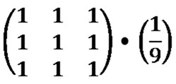
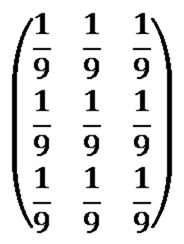
Every / element should be set to one. The resulting value should be multiplied by a factor value equating to one divided by the / size. As an example, a / size of 3×3 can be expressed as follows:

Mean Kernel

An alternative expression can also be:

Mean Kernel

Frog: Filter Size 9×9

Frog: Filter Size 9x9

Boolean Edge Detection without a local threshold

When performing Boolean Edge Detection a local threshold should be implemented in order to exclude . In this article we rely on the interference of in order to render a fuzzy effect. By not implementing a local threshold when performing Boolean Edge detection the sample source code ensures sufficient interference from .

The steps involved in performing Boolean Edge Detection without a local threshold can be described as follows:

  1. Calculate Neighbourhood Mean – Iterate each forming part of the source/input . Using a 3×3 size calculate the mean value of the neighbourhood surrounding the currently being iterated.
  2. Create Mean comparison Matrix – Once again using a 3×3 size compare each neighbourhood to the newly calculated mean value. Create a temporary 3×3 size , each element’s value should be the result of mean comparison. Should the value expressed by a neighbourhood exceed the mean value the corresponding temporary element should be set to one. When the calculated mean value exceeds the value of a neighbourhood the corresponding temporary  element should be set to zero.
  3. Compare Edge Masks – Using sixteen predefined edge masks compare the temporary created in the previous step to each edge mask. If the temporary matches one of the predefined edge masks multiply the specified factor to the currently being iterated.

Note: A detailed article on Boolean Edge detection implementing a local threshold can be found here:

Frog: Filter Size 9×9

Frog: Filter Size 9x9

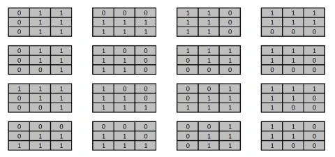
The sixteen predefined edge masks each represent an in a different direction. The predefined edge masks can be expressed as:

Boolean Edge Masks

Frog: Filter Size 13×13

Frog: Filter Size 13x13

Implementing a Mean Filter

The sample source code defines the MeanFilter method, an targeting the class. The definition listed as follows:

private static Bitmap MeanFilter(this Bitmap sourceBitmap, 
                                 int meanSize)
{
    byte[] pixelBuffer = sourceBitmap.GetByteArray(); 
    byte[] resultBuffer = new byte[pixelBuffer.Length];

double blue = 0.0, green = 0.0, red = 0.0; double factor = 1.0 / (meanSize * meanSize);
int imageStride = sourceBitmap.Width * 4; int filterOffset = meanSize / 2; int calcOffset = 0, filterY = 0, filterX = 0;
for (int k = 0; k + 4 < pixelBuffer.Length; k += 4) { blue = 0; green = 0; red = 0; filterY = -filterOffset; filterX = -filterOffset;
while (filterY <= filterOffset) { calcOffset = k + (filterX * 4) + (filterY * imageStride);
calcOffset = (calcOffset < 0 ? 0 : (calcOffset >= pixelBuffer.Length - 2 ? pixelBuffer.Length - 3 : calcOffset));
blue += pixelBuffer[calcOffset]; green += pixelBuffer[calcOffset + 1]; red += pixelBuffer[calcOffset + 2];
filterX++;
if (filterX > filterOffset) { filterX = -filterOffset; filterY++; } }
resultBuffer[k] = ClipByte(factor * blue); resultBuffer[k + 1] = ClipByte(factor * green); resultBuffer[k + 2] = ClipByte(factor * red); resultBuffer[k + 3] = 255; }
return resultBuffer.GetImage(sourceBitmap.Width, sourceBitmap.Height); }

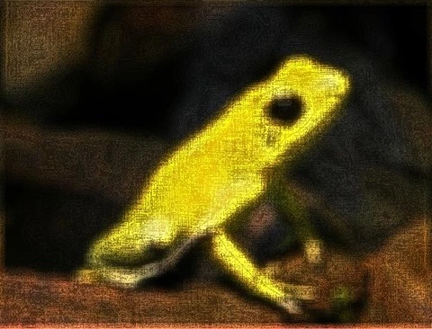
Frog: Filter Size 19×19

Frog: Filter Size 19x19

Implementing Boolean Edge Detection

Boolean Edge detection is performed in the sample source code through the implementation of the BooleanEdgeDetectionFilter method. This method has been defined as an targeting the class.

The following code snippet provides the definition of the BooleanEdgeDetectionFilter :

public static Bitmap BooleanEdgeDetectionFilter( 
       this Bitmap sourceBitmap, float edgeFactor) 
{
    byte[] pixelBuffer = sourceBitmap.GetByteArray(); 
    byte[] resultBuffer = new byte[pixelBuffer.Length]; 
    Buffer.BlockCopy(pixelBuffer, 0, resultBuffer, 
                     0, pixelBuffer.Length); 

List<string> edgeMasks = GetBooleanEdgeMasks(); int imageStride = sourceBitmap.Width * 4; int matrixMean = 0, pixelTotal = 0; int filterY = 0, filterX = 0, calcOffset = 0; string matrixPatern = String.Empty;
for (int k = 0; k + 4 < pixelBuffer.Length; k += 4) { matrixPatern = String.Empty; matrixMean = 0; pixelTotal = 0; filterY = -1; filterX = -1;
while (filterY < 2) { calcOffset = k + (filterX * 4) + (filterY * imageStride);
calcOffset = (calcOffset < 0 ? 0 : (calcOffset >= pixelBuffer.Length - 2 ? pixelBuffer.Length - 3 : calcOffset)); matrixMean += pixelBuffer[calcOffset]; matrixMean += pixelBuffer[calcOffset + 1]; matrixMean += pixelBuffer[calcOffset + 2];
filterX += 1;
if (filterX > 1) { filterX = -1; filterY += 1; } }
matrixMean = matrixMean / 9; filterY = -1; filterX = -1;
while (filterY < 2) { calcOffset = k + (filterX * 4) + (filterY * imageStride);
calcOffset = (calcOffset < 0 ? 0 : (calcOffset >= pixelBuffer.Length - 2 ? pixelBuffer.Length - 3 : calcOffset));
pixelTotal = pixelBuffer[calcOffset]; pixelTotal += pixelBuffer[calcOffset + 1]; pixelTotal += pixelBuffer[calcOffset + 2]; matrixPatern += (pixelTotal > matrixMean ? "1" : "0"); filterX += 1;
if (filterX > 1) { filterX = -1; filterY += 1; } }
if (edgeMasks.Contains(matrixPatern)) { resultBuffer[k] = ClipByte(resultBuffer[k] * edgeFactor);
resultBuffer[k + 1] = ClipByte(resultBuffer[k + 1] * edgeFactor);
resultBuffer[k + 2] = ClipByte(resultBuffer[k + 2] * edgeFactor); } }
return resultBuffer.GetImage(sourceBitmap.Width, sourceBitmap.Height); }

Frog: Filter Size 13×13

Frog: Filter Size 13x13

The predefined edge masks implemented in mean comparison have been wrapped by the GetBooleanEdgeMasks method. The definition as follows:

public static List<string> GetBooleanEdgeMasks() 
{
    List<string> edgeMasks = new List<string>(); 

edgeMasks.Add("011011011"); edgeMasks.Add("000111111"); edgeMasks.Add("110110110"); edgeMasks.Add("111111000"); edgeMasks.Add("011011001"); edgeMasks.Add("100110110"); edgeMasks.Add("111011000"); edgeMasks.Add("111110000"); edgeMasks.Add("111011001"); edgeMasks.Add("100110111"); edgeMasks.Add("001011111"); edgeMasks.Add("111110100"); edgeMasks.Add("000011111"); edgeMasks.Add("000110111"); edgeMasks.Add("001011011"); edgeMasks.Add("110110100");
return edgeMasks; }

Frog: Filter Size 19×19

Frog: Filter Size 19x19

Implementing a Fuzzy Blur Filter

The FuzzyEdgeBlurFilter method serves as the implementation of a Fuzzy Blur Filter. As discussed earlier a Fuzzy Blur Filter involves enhancing through Boolean Edge detection, performing a blur and then once again performing Boolean Edge detection. This method has been defined as an extension method targeting the class.

The following code snippet provides the definition of the FuzzyEdgeBlurFilter method:

public static Bitmap FuzzyEdgeBlurFilter(this Bitmap sourceBitmap,  
                                         int filterSize,  
                                         float edgeFactor1,  
                                         float edgeFactor2) 
{
    return  
    sourceBitmap.BooleanEdgeDetectionFilter(edgeFactor1). 
    MeanFilter(filterSize).BooleanEdgeDetectionFilter(edgeFactor2); 
}

Frog: Filter Size 3×3

Frog: Filter Size 3x3

Sample Images

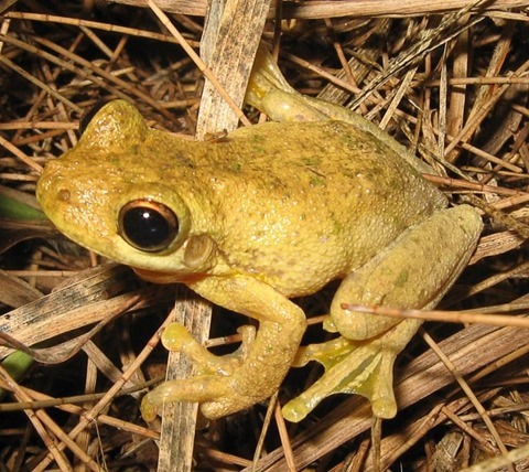
This article features a number of sample images. All featured images have been licensed allowing for reproduction. The following images feature as sample images:

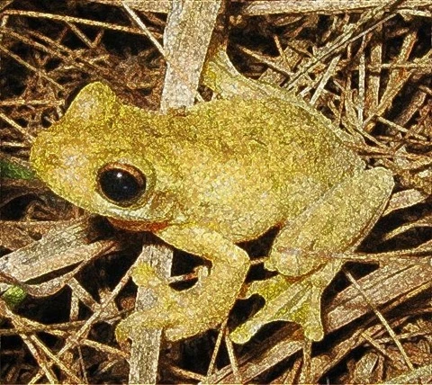
Litoria_tyleri

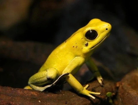
Schrecklicherpfeilgiftfrosch-01

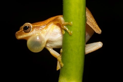
Dendropsophus_microcephalus_-_calling_male_(Cope,_1886)

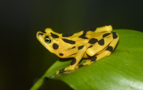
Atelopus_zeteki1

Related Articles and Feedback

Feedback and questions are always encouraged. If you know of an alternative implementation or have ideas on a more efficient implementation please share in the comments section.

I’ve published a number of articles related to imaging and images of which you can find URL links here:

C# How to: Image Abstract Colours Filter
Article Purpose

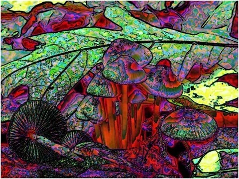
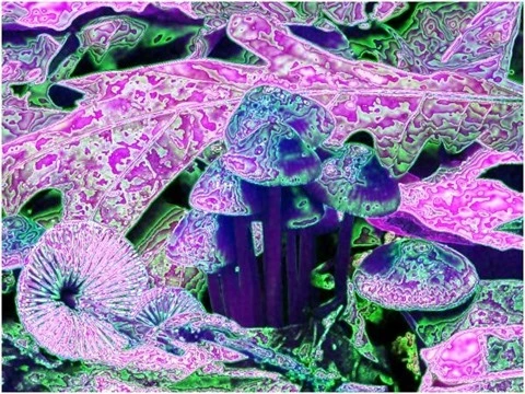
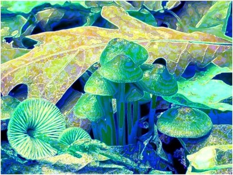
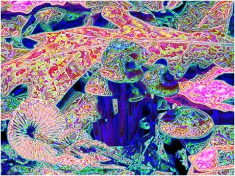
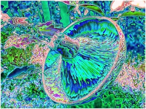
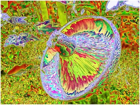
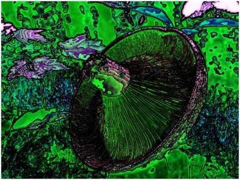
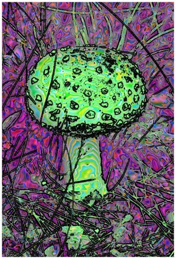
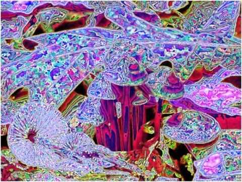
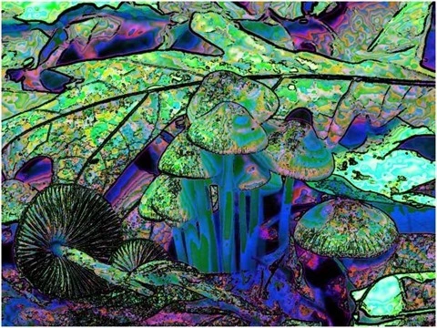
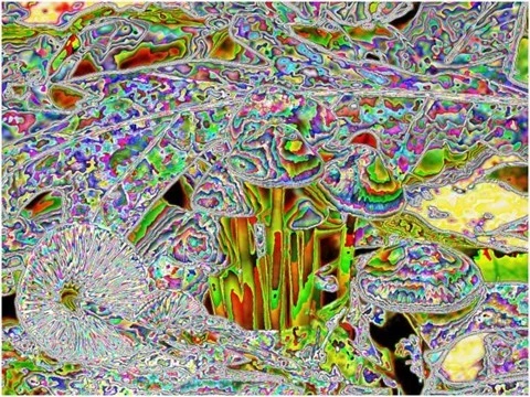
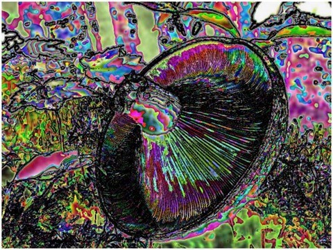
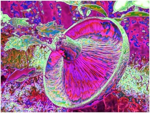
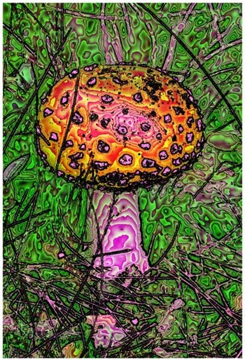
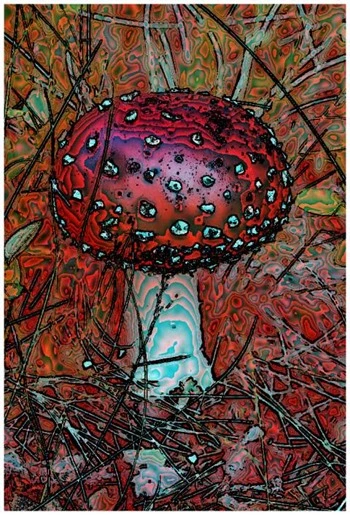
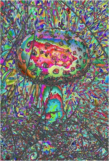
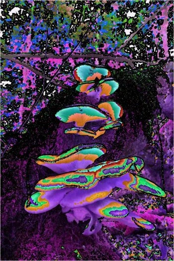
This article explores Abstract Colour Image filters as a process of Non-photo Realistic Image Rendering. The output produced reflects a variety of artistic effects.

Colour Values Red, Blue Filter Size 9
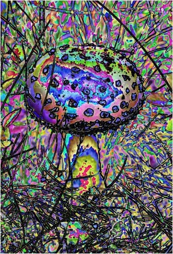
Edge Tracing Black Edge Threshold 55

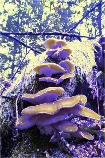
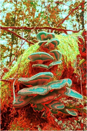
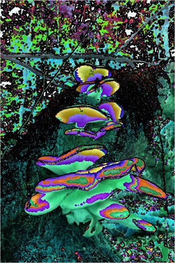
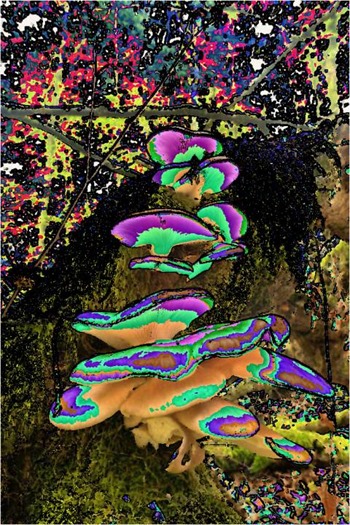
Mushroom: Red - Blue, Filter Size 9, Edge Tracing Black, Edge Threshold 55
Sample Source Code

This article is accompanied by a sample source code Visual Studio project which is available for download .

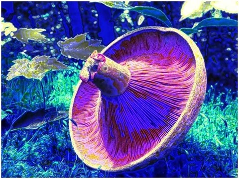
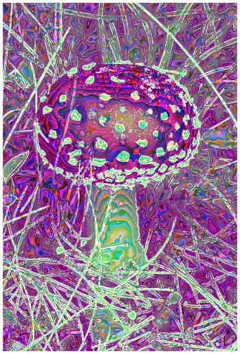
Colour Values Blue Filter Size 9
Edge Tracing Double Intensity Edge Threshold 60

Mushroom: Blue, Filter Size 9, Color Shift Right, Edge Tracing Double Intensity, Edge Threshold 60

Using the Sample Application

The sample source code that accompanies this article includes a based sample application. The concepts discussed in this article have been illustrated through the implementation of the sample application.

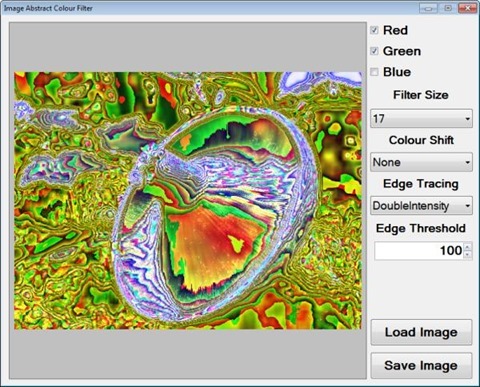
When executing the sample application, through the user interface several options are made available to the user, described as follows:

  • Load/Save Source/input may be loaded from the local system through clicking the Load Image button. If desired by the user, resulting output can be saved to the local file system through clicking the Save Image button.
  • Colour Channels – The colour values Red, Green and Blue can be updated or remain unchanged when applying a filter, indicated through the associated .
  • Filter Size – The level of filter intensity depends on the size of the filter. Larger filter sizes result in more intense filtering being applied. Smaller filter size result in less intense filtering being applied.
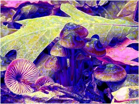
  • Colour Shift Type – Colour intensity values can be swapped around through selecting the Colour Shift type: Shift Left and Shift Right.
  • Edge Tracing Type – When applying a filter the edges forming part of the original source/input will be expressed as part of the output . The method in which are indicated/highlighted will be determined through the type of Edge Tracing specified when applying the filter. Supported types of Edge Tracing include: Black, White, Half Intensity, Double Intensity and Inverted.
  • Edge Threshold – Edges forming part of the source/input are determines through means of implementing a threshold value. Lower threshold values result in more emphasized edges expressed within resulting . Higher threshold values reduce edge emphasis in resulting .


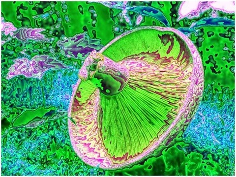
Colour Values Green Filter Size 9
Edge Tracing Double Intensity Edge Threshold 60

Mushroom: Green, Filter Size 9, Color Shift Left, Edge Tracing Double Intensity, Edge Threshold 60

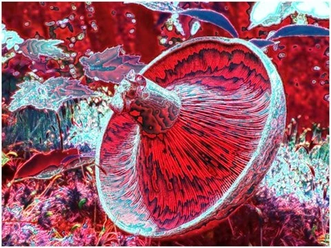
Colour Values Red, Blue Filter Size 9
Edge Tracing Double Intensity Edge Threshold 55

Mushroom: Red - Blue, Filter Size 9, Color Shift Right, Edge Tracing Double Intensity, Edge Threshold 55

The following image is a screenshot of the Image Abstract Colour Filter sample application in action:

Image Abstract Colour Filter Sample Application

Abstracting Image Colours

The Abstract Colour Filter explored in this article can be considered a non-photo realistic filter. As the title implies, non-photo realistic filters transforms an input , usually a photograph, producing a result which visibly lacks the aspects of realism expressed in the input . In most scenarios the objective of non-photo realistic filters can be described as using photographic in rendering having an animated appearance.

Colour Values Blue Filter Size 11
Edge Tracing Double Intensity Edge Threshold 60

Mushroom: Blue, Filter Size 11, Color Shift Left, Edge Tracing Double Intensity, Edge Threshold 60

Colour Values Red Filter Size 11
Edge Tracing Double Intensity Edge Threshold 60

Mushroom: Red, Filter Size 11, Color Shift Left, Edge Tracing Double Intensity, Edge Threshold 60

The Abstract Colour Filter can be broken down into two main components: Colour Averaging and . Through implementing a variety of colour averaging algorithms resulting express abstract yet uniform colours. Abstract colours result in output no longer appearing photo realistic, instead output appear unconventionally augmented/artistic.

Output express a lesser degree of definition and detail, when compared to input . In some scenarios output might not be easily recognisable. In order to retain some detail, edge/boundary detail detected from input will be emphasised in result .

Colour Values Green Filter Size 11
Edge Tracing Double Intensity Edge Threshold 60

Mushroom: Green, Filter Size 11, Color Shift Left, Edge Tracing, Double Intensity, Edge Threshold 60

Colour Values Green, Blue Filter Size 11
Edge Tracing Double Intensity Edge Threshold 75

Mushroom: Green - Blue, Filter Size 11, Color Shift None, Edge Tracing Double Intensity, Edge Threshold 75

The steps required when applying an Abstract Colour Filter can be described as follows:

  1. Perform – Using the source/input perform , producing a binary expressing in the foreground/as white.
  2. Calculate Neighbourhood Colour Averages – Iterate each forming part of the input , inspecting the ’s neighbouring . Calculate the sum total and average of each colour channel, Red, Green and Blue. The value of the currently being iterated should be set depending to neighbourhood average.
  3. Trace Edges within Colour Averages – Simultaneously iterate the colour average and the edge detected . If the being iterated forms part of an edge, update the corresponding in the average colour , depending on the specified method of Edge Tracing.


Colour Values Red, Green Filter Size 11
Edge Tracing Double Intensity Edge Threshold 75

Mushroom: Red - Green, Filter Size 11, Color Shift None, Edge Tracing Double Intensity, Edge Threshold 75

Colour Values Red Filter Size 11
Edge Tracing Black Edge Threshold 60

Mushroom: Red, Filter Size 11, Color Shift Left, Edge Tracing Black, Edge Threshold 60

Implementing Pixel Neighbourhood Colour Averaging

In the sample source code neighbourhood colour averaging has been implemented through the definition of the AverageColoursFilter . This method creates a new using the source as input. The following code snippet provides the definition:

public static Bitmap AverageColoursFilter(this Bitmap sourceBitmap,  
                                          int matrixSize,   
                                          bool applyBlue = true, 
                                          bool applyGreen = true, 
                                          bool applyRed = true, 
                                          ColorShiftType shiftType = 
                                          ColorShiftType.None)  
{
    byte[] pixelBuffer = sourceBitmap.GetByteArray(); 
    byte[] resultBuffer = new byte[pixelBuffer.Length]; 

int calcOffset = 0; int byteOffset = 0; int blue = 0; int green = 0; int red = 0; int filterOffset = (matrixSize - 1) / 2;
for (int offsetY = filterOffset; offsetY < sourceBitmap.Height - filterOffset; offsetY++) { for (int offsetX = filterOffset; offsetX < sourceBitmap.Width - filterOffset; offsetX++) { byteOffset = offsetY * sourceBitmap.Width*4 + offsetX * 4;
blue = 0; green = 0; red = 0;
for (int filterY = -filterOffset; filterY <= filterOffset; filterY++) { for (int filterX = -filterOffset; filterX <= filterOffset; filterX++) { calcOffset = byteOffset + (filterX * 4) + (filterY * sourceBitmap.Width * 4);
blue += pixelBuffer[calcOffset]; green += pixelBuffer[calcOffset + 1]; red += pixelBuffer[calcOffset + 2]; } }
blue = blue / matrixSize; green = green / matrixSize; red = red / matrixSize;
if (applyBlue == false ) { blue = pixelBuffer[byteOffset]; }
if (applyGreen == false ) { green = pixelBuffer[byteOffset + 1]; }
if (applyRed == false ) { red = pixelBuffer[byteOffset + 2]; }
if (shiftType == ColorShiftType.None) { resultBuffer[byteOffset] = (byte)blue; resultBuffer[byteOffset + 1] = (byte)green; resultBuffer[byteOffset + 2] = (byte)red; resultBuffer[byteOffset + 3] = 255; } else if (shiftType == ColorShiftType.ShiftLeft) { resultBuffer[byteOffset] = (byte)green; resultBuffer[byteOffset + 1] = (byte)red; resultBuffer[byteOffset + 2] = (byte)blue; resultBuffer[byteOffset + 3] = 255; } else if (shiftType == ColorShiftType.ShiftRight) { resultBuffer[byteOffset] = (byte)red; resultBuffer[byteOffset + 1] = (byte)blue; resultBuffer[byteOffset + 2] = (byte)green; resultBuffer[byteOffset + 3] = 255; } } }
Bitmap resultBitmap = new Bitmap(sourceBitmap.Width, sourceBitmap.Height);
BitmapData resultData = resultBitmap.LockBits(new Rectangle (0, 0, resultBitmap.Width, resultBitmap.Height), ImageLockMode.WriteOnly, PixelFormat.Format32bppArgb);
Marshal.Copy(resultBuffer, 0, resultData.Scan0, resultBuffer.Length);
resultBitmap.UnlockBits(resultData);
return resultBitmap; }
Colour Values Green, Blue Filter Size 17
Edge Tracing Black Edge Threshold 85

Mushroom: Green - Blue, Filter Size 17, Color Shift Left, Edge Tracing Black, Edge Threshold 85

Implementing Gradient Based Edge Detection

When applying an Abstract Colours Filter, one of the required steps involve . The sample source code implements   through the definition of the GradientBasedEdgeDetectionFilter method. This method has been defined as an targeting the class. The as follows:

public static Bitmap GradientBasedEdgeDetectionFilter( 
                        this Bitmap sourceBitmap, 
                        byte threshold = 0) 
{
    BitmapData sourceData = 
               sourceBitmap.LockBits(new Rectangle (0, 0, 
               sourceBitmap.Width, sourceBitmap.Height), 
               ImageLockMode.ReadOnly, 
               PixelFormat.Format32bppArgb); 

byte[] pixelBuffer = new byte[sourceData.Stride * sourceData.Height]; byte[] resultBuffer = new byte[sourceData.Stride * sourceData.Height];
Marshal.Copy(sourceData.Scan0, pixelBuffer, 0, pixelBuffer.Length); sourceBitmap.UnlockBits(sourceData);
int sourceOffset = 0, gradientValue = 0; bool exceedsThreshold = false;
for (int offsetY = 1; offsetY < sourceBitmap.Height - 1; offsetY++) { for (int offsetX = 1; offsetX < sourceBitmap.Width - 1; offsetX++) { sourceOffset = offsetY * sourceData.Stride + offsetX * 4; gradientValue = 0; exceedsThreshold = true;
// Horizontal Gradient CheckThreshold(pixelBuffer, sourceOffset - 4, sourceOffset + 4, ref gradientValue, threshold, 2); // Vertical Gradient exceedsThreshold = CheckThreshold(pixelBuffer, sourceOffset - sourceData.Stride, sourceOffset + sourceData.Stride, ref gradientValue, threshold, 2);
if (exceedsThreshold == false) { gradientValue = 0;
// Horizontal Gradient exceedsThreshold = CheckThreshold(pixelBuffer, sourceOffset - 4, sourceOffset + 4, ref gradientValue, threshold);
if (exceedsThreshold == false) { gradientValue = 0;
// Vertical Gradient exceedsThreshold = CheckThreshold(pixelBuffer, sourceOffset - sourceData.Stride, sourceOffset + sourceData.Stride, ref gradientValue, threshold);
if (exceedsThreshold == false) { gradientValue = 0;
// Diagonal Gradient : NW-SE CheckThreshold(pixelBuffer, sourceOffset - 4 - sourceData.Stride, sourceOffset + 4 + sourceData.Stride, ref gradientValue, threshold, 2); // Diagonal Gradient : NE-SW exceedsThreshold = CheckThreshold(pixelBuffer, sourceOffset - sourceData.Stride + 4, sourceOffset - 4 + sourceData.Stride, ref gradientValue, threshold, 2);
if (exceedsThreshold == false) { gradientValue = 0;
// Diagonal Gradient : NW-SE exceedsThreshold = CheckThreshold(pixelBuffer, sourceOffset - 4 - sourceData.Stride, sourceOffset + 4 + sourceData.Stride, ref gradientValue, threshold);
if (exceedsThreshold == false) { gradientValue = 0;
// Diagonal Gradient : NE-SW exceedsThreshold = CheckThreshold(pixelBuffer, sourceOffset - sourceData.Stride + 4, sourceOffset + sourceData.Stride - 4, ref gradientValue, threshold); } } } } }
resultBuffer[sourceOffset] = (byte)(exceedsThreshold ? 255 : 0); resultBuffer[sourceOffset + 1] = resultBuffer[sourceOffset]; resultBuffer[sourceOffset + 2] = resultBuffer[sourceOffset]; resultBuffer[sourceOffset + 3] = 255; } }
Bitmap resultBitmap = new Bitmap(sourceBitmap.Width, sourceBitmap.Height);
BitmapData resultData = resultBitmap.LockBits(new Rectangle (0, 0, resultBitmap.Width, resultBitmap.Height), ImageLockMode.WriteOnly, PixelFormat.Format32bppArgb);
Marshal.Copy(resultBuffer, 0, resultData.Scan0, resultBuffer.Length); resultBitmap.UnlockBits(resultData);
return resultBitmap; }
Colour Values Red, Green Filter Size 5
Edge Tracing Black Edge Threshold 85

Mushroom: Red - Green - Blue, Filter Size 5, Color Shift Right, Edge Tracing Black, Edge Threshold 85

Implementing an Abstract Colour Filter

The AbstractColorsFilter method serves as means of combining an average colour and an edge detected . This targets the class. The following code snippet details the definition:

public static Bitmap AbstractColorsFilter(this Bitmap sourceBitmap, 
                                          int matrixSize, 
                                          byte edgeThreshold, 
                                          bool applyBlue = true, 
                                          bool applyGreen = true, 
                                          bool applyRed = true, 
                                          EdgeTracingType edgeType =  
                                          EdgeTracingType.Black, 
                                          ColorShiftType shiftType = 
                                          ColorShiftType.None) 
{ 
    Bitmap edgeBitmap =  
    sourceBitmap.GradientBasedEdgeDetectionFilter(edgeThreshold); 

Bitmap colorBitmap = sourceBitmap.AverageColoursFilter(matrixSize, applyBlue, applyGreen, applyRed, shiftType);
byte[] edgeBuffer = edgeBitmap.GetByteArray(); byte[] colorBuffer = colorBitmap.GetByteArray(); byte[] resultBuffer = colorBitmap.GetByteArray();
for (int k = 0; k + 4 < edgeBuffer.Length; k += 4) { if (edgeBuffer[k] == 255) { switch (edgeType) { case EdgeTracingType.Black: resultBuffer[k] = 0; resultBuffer[k+1] = 0; resultBuffer[k+2] = 0; break; case EdgeTracingType.White: resultBuffer[k] = 255; resultBuffer[k+1] = 255; resultBuffer[k+2] = 255; break; case EdgeTracingType.HalfIntensity: resultBuffer[k] = ClipByte(resultBuffer[k] * 0.5); resultBuffer[k + 1] = ClipByte(resultBuffer[k + 1] * 0.5); resultBuffer[k + 2] = ClipByte(resultBuffer[k + 2] * 0.5); break; case EdgeTracingType.DoubleIntensity: resultBuffer[k] = ClipByte(resultBuffer[k] * 2); resultBuffer[k + 1] = ClipByte(resultBuffer[k + 1] * 2); resultBuffer[k + 2] = ClipByte(resultBuffer[k + 2] * 2); break; case EdgeTracingType.ColorInversion: resultBuffer[k] = ClipByte(255 - resultBuffer[k]); resultBuffer[k+1] = ClipByte(255 - resultBuffer[k+1]); resultBuffer[k+2] = ClipByte(255 - resultBuffer[k+2]); break; } } }
Bitmap resultBitmap = new Bitmap (sourceBitmap.Width, sourceBitmap.Height);
BitmapData resultData = resultBitmap.LockBits(new Rectangle (0, 0, resultBitmap.Width, resultBitmap.Height), ImageLockMode.WriteOnly, PixelFormat.Format32bppArgb);
Marshal.Copy(resultBuffer, 0, resultData.Scan0, resultBuffer.Length);
resultBitmap.UnlockBits(resultData);
return resultBitmap; }
Colour Values Red, Green Filter Size 17
Edge Tracing Double Intensity Edge Threshold 85

Mushroom: Red - Green, Filter Size 17, Color Shift None, Edge Tracing Double Intensity, Edge Threshold 85

Sample Images

This article features a number of sample images. All featured images have been licensed allowing for reproduction. The following images feature as sample images:

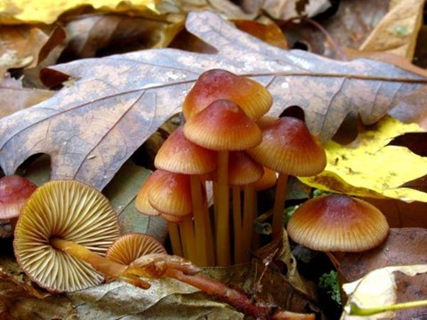
1280px-Mycena_atkinsoniana_60804

1024px-Lactarius_indigo_48568

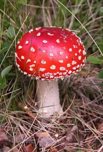
Amanita_muscaria_(fly_agaric)

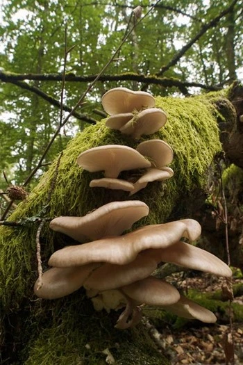
683px-Pleurotus_pulmonarius_LC0228

Additional Filter Result Images

The following series of images represent additional filter results.

Colour Values Red Filter Size 9
Edge Tracing Double Intensity Edge Threshold 60

Mushroom: Red, Filter Size 9, Color Shift Right, Edge Tracing Double, Edge Threshold 60

Colour Values Green, Blue Filter Size 9
Edge Tracing Double Intensity Edge Threshold 60

Mushroom: Green - Blue, Filter Size 9, Color Shift Right, Edge Tracing Double Intensity, Edge Threshold 60

Colour Values Green, Blue Filter Size 9
Edge Tracing Black Edge Threshold 60

Mushroom: Green - Blue, Filter Size 9, Color Shift Left, Edge Tracing Black, Edge Threshold 60

Colour Values Red, Green, Blue Filter Size 9
Edge Tracing Double Intensity Edge Threshold 55

Mushroom: Red - Green - Blue, Filter Size 9, Color Shift None, Edge Tracing Double Intensity, Edge Threshold 55

Colour Values Red, Green, Blue Filter Size 11
Edge Tracing Black Edge Threshold 75

Mushroom: Red - Green - Blue, Filter Size 11, Color Shift None, Edge Tracing Black, Edge Threshold 75

Colour Values Red, Blue Filter Size 11
Edge Tracing Double Intensity Edge Threshold 75

Mushroom: Red - Blue, Filter Size 11, Color Shift None, Edge Tracing Double Intensity, Edge Threshold 75

Colour Values Green Filter Size 17
Edge Tracing Black Edge Threshold 85

Mushroom: Green, Filter Size 17, Color Shift None, Edge Tracing Black, Edge Threshold 85

Colour Values Red Filter Size 17
Edge Tracing Black Edge Threshold 85

Mushroom: Red, Filter Size 17, Color Shift None, Edge Tracing Black, Edge Threshold 85

Colour Values Red, Green, Blue Filter Size 5
Edge Tracing Half Edge Edge Threshold 85

Mushroom: Red - Green - Blue, Filter Size 5, Color Shift None, Edge Tracing Half Edge, Threshold 85

Colour Values Blue Filter Size 5
Edge Tracing Double Intensity Edge Threshold 75

Mushroom: Blue, FilterSize 5, Color Shift None, Edge Tracing Double Intensity, Edge Threshold 75

Colour Values Green Filter Size 5
Edge Tracing Double Intensity Edge Threshold 75

Mushroom: Green, Filter Size 5, Color Shift None, Edge Tracing Double Intensity, Edge Threshold 75

Colour Values Red Filter Size 5
Edge Tracing Double Intensity Edge Threshold 75

Mushroom: Red, Filter Size 5, Color Shift None, Edge Tracing Double Intensity, Edge Threshold 75

Colour Values Red, Green, Blue Filter Size 5
Edge Tracing Black Edge Threshold 75

Mushroom: Red - Green - Blue, Filter Size 3, Color Shift Left, Edge Tracing Black, Edge Threshold 75

Colour Values Red, Green, Blue Filter Size 9
Edge Tracing Black Edge Threshold 55

Mushroom: Red - Green - Blue, Filter Size 3, Color Shift None, Edge Tracing Black, Edge Threshold 75

Colour Values Red, Green, Blue Filter Size 3
Edge Tracing Black Edge Threshold 75

Mushroom: Red - Green - Blue, Filter Size 3, Color Shift Right, Edge Tracing Black, Edge Threshold 75

Related Articles and Feedback

Feedback and questions are always encouraged. If you know of an alternative implementation or have ideas on a more efficient implementation please share in the comments section.

I’ve published a number of articles related to imaging and images of which you can find URL links here:

C# How to: Image Boundary Extraction

Article Purpose

This article explores various concepts, which feature in combination when implementing Image Boundary Extraction. Concepts covered within this article include: Morphological and , Addition and Subtraction, Boundary Sharpening, Boundary Tracing and Boundary Extraction.

Parrot: Boundary Extraction, 3×3, Red, Green, Blue

Parrot: Boundary Extraction, 3x3, Red, Greed, Blue

Sample Source Code

This article is accompanied by a sample source code Visual Studio project which is available for download .

Using the Sample Application

This article’s accompanying sample source code includes the definition of a sample application. The sample application serves as an implementation of the concepts discussed in this article. In using the sample application concepts can be easily tested and replicated.

The sample application has been defined as a . The user interface enables the user to configure several options which influence the output produced from filtering processes. The following section describes the options available to a user when executing the sample application:

  • Loading and Saving files – Users can specify source/input through clicking the Load Image button. If desired, resulting filtered can be saved to the local system when clicking the Save Image button.
  • Filter Type – The types of filters implemented represent variations on Image Boundary Extraction. The supported filter types are: Conventional Boundary extraction, Boundary Sharpening and Boundary Tracing.
  • Filter Size – Filter intensity/strength will mostly be reliant on the filter size implemented. A Filter size represents the number of neighbouring examined when applying filters.
  • Colours Applied – The sample source code and sample application provides functionality allowing a filter to only effect user specified colour components. Colour components are represented in the form of an RGB colour scheme. The inclusion or exclusion of the colour components Red, Green and Blue will be determined through user configuration.
  • Structuring Element – As mentioned, the Filter Size option determines the size of neighbourhood examined. The ’s setup determine the neighbouring   within the neighbourhood size bounds that should be used as input when calculating filter results.

The following is a screenshot of the Image Boundary Extraction sample application in action:

Image Boundary Extaction Sample  Application

Parrot: Boundary Extraction, 3×3, Green

Parrot: Boundary Extraction, 3x3, Green

Morphological Boundary Extraction

Image Boundary Extraction can be considered a method of . In contrast to more commonly implemented   methods, Image Boundary Extraction originates from Morphological Image Filters.

When drawing a comparison, Image Boundary Extraction and express strong similarities. results from the difference in and . Considered from a different point of view, creating one expressing thicker edges and another expressing thinner edges provides the means to calculate the difference in edges.

Image Boundary Extraction implements the same concept as . The base concept can be regarded as calculating the difference between two which rendered the same , but expressing a difference in . Image Boundary Extraction relies on calculating the difference between either and the source or and the source . The difference between and in most cases result in more of difference than the difference between and the source or and the source . The result of Image Boundary Extraction representing less of a difference than can be observed in Image Boundary Extraction being expressed in finer/smaller width lines.

is another method of which functions along the same basis. Edges are determined by calculating the difference between two , each having been filtered from the same source , using a of differing intensity levels.

Parrot: Boundary Extraction, 3×3, Red, Green, Blue

Parrot: Boundary Extraction, 3x3, Red, Green, Blue

Boundary Sharpening

The concept of Boundary Sharpening refers to enhancing or sharpening the boundaries or edges expressed in a source/input . Boundaries can be easily determined or extracted as discussed earlier when exploring Boundary Extraction.

The steps involved in performing Boundary Sharpening can be described as follows:

  1. Extract Boundaries – Determine boundaries by performing and calculating the difference between the dilated and the source .
  2. Match Source Edges and Extracted Boundaries – The boundaries extracted in the previous step represent the difference between and the original source . Ensure that extracted boundaries match the source through performing on a copy of the source/input .
  3. Emphasise Extracted boundaries in source image – Perform addition using the extracted boundaries and dilated copy of the source .

Parrot: Boundary Extraction, 3×3, Red, Green, Blue

Parrot: Boundary Extraction, 3x3, Red, Green, Blue

Boundary Tracing

Boundary Tracing refers to applying filters which result in /boundaries appearing darker or more pronounced. This type of filter also relies on Boundary Extraction.

Boundary Tracing can be implemented in two steps, described as follows:

  1. Extract Boundaries – Determine boundaries by performing and calculating the difference between the dilated and the source .
  2. Emphasise Extracted boundaries in source image – Subtract the extracted boundaries from the original source .

Parrot: Boundary Extraction, 3×3, Red, Green, Blue

Parrot: Boundary Extraction, 3x3, Red, Green, Blue

Implementing Morphological Erosion and Dilation

The accompanying sample source code defines the MorphologyOperation method,  defined as an targeting the class. In terms of parameters this method expects a two dimensional array representing a . The other required  parameter represents an value indicating which Morphological Operation to perform, either or .

The following code snippet provides the definition in full:

private static Bitmap MorphologyOperation(this Bitmap sourceBitmap,
                                          bool[,] se,
                                          MorphologyOperationType morphType,
                                          bool applyBlue = true,
                                          bool applyGreen = true,
                                          bool applyRed = true)
{ 
    BitmapData sourceData =
               sourceBitmap.LockBits(new Rectangle(0, 0,
               sourceBitmap.Width, sourceBitmap.Height),
               ImageLockMode.ReadOnly,
               PixelFormat.Format32bppArgb);

byte[] pixelBuffer = new byte[sourceData.Stride * sourceData.Height];
byte[] resultBuffer = new byte[sourceData.Stride * sourceData.Height];
Marshal.Copy(sourceData.Scan0, pixelBuffer, 0, pixelBuffer.Length);
sourceBitmap.UnlockBits(sourceData);
int filterOffset = (se.GetLength(0) - 1) / 2; int calcOffset = 0, byteOffset = 0; byte blueErode = 0, greenErode = 0, redErode = 0; byte blueDilate = 0, greenDilate = 0, redDilate = 0;
for (int offsetY = 0; offsetY < sourceBitmap.Height - filterOffset; offsetY++) { for (int offsetX = 0; offsetX < sourceBitmap.Width - filterOffset; offsetX++) { byteOffset = offsetY * sourceData.Stride + offsetX * 4;
blueErode = 255; greenErode = 255; redErode = 255; blueDilate = 0; greenDilate = 0; redDilate = 0;
for (int filterY = -filterOffset; filterY <= filterOffset; filterY++) { for (int filterX = -filterOffset; filterX <= filterOffset; filterX++) { if (se[filterY + filterOffset, filterX + filterOffset] == true) { calcOffset = byteOffset + (filterX * 4) + (filterY * sourceData.Stride);
calcOffset = (calcOffset < 0 ? 0 : (calcOffset >= pixelBuffer.Length + 2 ? pixelBuffer.Length - 3 : calcOffset));
blueDilate = (pixelBuffer[calcOffset] > blueDilate ? pixelBuffer[calcOffset] : blueDilate);
greenDilate = (pixelBuffer[calcOffset + 1] > greenDilate ? pixelBuffer[calcOffset + 1] : greenDilate);
redDilate = (pixelBuffer[calcOffset + 2] > redDilate ? pixelBuffer[calcOffset + 2] : redDilate);
blueErode = (pixelBuffer[calcOffset] < blueErode ? pixelBuffer[calcOffset] : blueErode);
greenErode = (pixelBuffer[calcOffset + 1] < greenErode ? pixelBuffer[calcOffset + 1] : greenErode);
redErode = (pixelBuffer[calcOffset + 2] < redErode ? pixelBuffer[calcOffset + 2] : redErode); } } }
blueErode = (applyBlue ? blueErode : pixelBuffer[byteOffset]); blueDilate = (applyBlue ? blueDilate : pixelBuffer[byteOffset]);
greenErode = (applyGreen ? greenErode : pixelBuffer[byteOffset + 1]); greenDilate = (applyGreen ? greenDilate : pixelBuffer[byteOffset + 1]);
redErode = (applyRed ? redErode : pixelBuffer[byteOffset + 2]); redDilate = (applyRed ? redDilate : pixelBuffer[byteOffset + 2]);
if (morphType == MorphologyOperationType.Erosion) { resultBuffer[byteOffset] = blueErode; resultBuffer[byteOffset + 1] = greenErode; resultBuffer[byteOffset + 2] = redErode; } else if (morphType == MorphologyOperationType.Dilation) { resultBuffer[byteOffset] = blueDilate; resultBuffer[byteOffset + 1] = greenDilate; resultBuffer[byteOffset + 2] = redDilate; }
resultBuffer[byteOffset + 3] = 255; } }
Bitmap resultBitmap = new Bitmap(sourceBitmap.Width, sourceBitmap.Height); BitmapData resultData = resultBitmap.LockBits(new Rectangle(0, 0, resultBitmap.Width, resultBitmap.Height), ImageLockMode.WriteOnly, PixelFormat.Format32bppArgb);
Marshal.Copy(resultBuffer, 0, resultData.Scan0, resultBuffer.Length);
resultBitmap.UnlockBits(resultData);
return resultBitmap; }

Parrot: Boundary Extraction, 3×3, Red, Green

Parrot: Boundary Extraction, 3x3, Red, Green

Implementing Image Addition

The sample source code encapsulates the process of combining two separate through means of addition. The AddImage method serves as a single declaration of addition functionality. This method has been defined as an targeting the class. Boundary Sharpen filtering implements addition.

The following code snippet provides the definition of the AddImage :

private static Bitmap AddImage(this Bitmapsource Bitmap, 
                               Bitmap addBitmap)
{
    BitmapData sourceData =
               sourceBitmap.LockBits(new Rectangle (0, 0,
               sourceBitmap.Width, sourceBitmap.Height),
               ImageLockMode.ReadOnly,
               PixelFormat.Format32bppArgb);

byte[] resultBuffer = new byte[sourceData.Stride * sourceData.Height];
Marshal.Copy(sourceData.Scan0, resultBuffer, 0, resultBuffer.Length);
sourceBitmap.UnlockBits(sourceData);
BitmapData addData = addBitmap.LockBits(new Rectangle(0, 0, addBitmap.Width, addBitmap.Height), ImageLockMode.ReadOnly, PixelFormat.Format32bppArgb);
byte[] addBuffer = new byte[addData.Stride * addData.Height];
Marshal.Copy(addData.Scan0, addBuffer, 0, addBuffer.Length);
addBitmap.UnlockBits(addData);
for (int k = 0; k + 4 < resultBuffer.Length && k + 4 < addBuffer.Length; k += 4) { resultBuffer[k] = AddColors(resultBuffer[k], addBuffer[k]); resultBuffer[k + 1] = AddColors(resultBuffer[k + 1], addBuffer[k + 1]); resultBuffer[k + 2] = AddColors(resultBuffer[k + 2], addBuffer[k + 2]); resultBuffer[k + 3] = 255; }
Bitmap resultBitmap = new Bitmap(sourceBitmap.Width, sourceBitmap.Height);
BitmapData resultData = resultBitmap.LockBits(new Rectangle(0, 0, resultBitmap.Width, resultBitmap.Height), ImageLockMode.WriteOnly, PixelFormat.Format32bppArgb);
Marshal.Copy(resultBuffer, 0, resultData.Scan0, resultBuffer.Length);
resultBitmap.UnlockBits(resultData);
return resultBitmap; }
private static byte AddColors(byte color1, byte color2) 
{
    int result = color1 + color2; 

return (byte)(result < 0 ? 0 : (result > 255 ? 255 : result)); }

Parrot: Boundary Extraction, 3×3, Red, Green, Blue

Parrot: Boundary Extraction, 3x3, Red, Green, Blue

Implementing Image Subtraction

In a similar fashion regarding the AddImage method the sample code defines the SubractImage method.  By definition this method serves as an targeting the class. Image subtraction has been implemented in Boundary Extraction and Boundary Tracing.

The definition of the SubtractImage method listed as follows:

private static Bitmap SubtractImage(this Bitmap sourceBitmap,  
                                         Bitmap subtractBitmap) 
{
    BitmapData sourceData = 
               sourceBitmap.LockBits(new Rectangle(0, 0, 
               sourceBitmap.Width, sourceBitmap.Height), 
               ImageLockMode.ReadOnly, 
               PixelFormat.Format32bppArgb); 

byte[] resultBuffer = new byte[sourceData.Stride * sourceData.Height];
Marshal.Copy(sourceData.Scan0, resultBuffer, 0, resultBuffer.Length);
sourceBitmap.UnlockBits(sourceData);
BitmapData subtractData = subtractBitmap.LockBits(new Rectangle(0, 0, subtractBitmap.Width, subtractBitmap.Height), ImageLockMode.ReadOnly, PixelFormat.Format32bppArgb);
byte[] subtractBuffer = new byte[subtractData.Stride * subtractData.Height];
Marshal.Copy(subtractData.Scan0, subtractBuffer, 0, subtractBuffer.Length);
subtractBitmap.UnlockBits(subtractData);
for (int k = 0; k + 4 < resultBuffer.Length && k + 4 < subtractBuffer.Length; k += 4) { resultBuffer[k] = SubtractColors(resultBuffer[k], subtractBuffer[k]);
resultBuffer[k + 1] = SubtractColors(resultBuffer[k + 1], subtractBuffer[k + 1]);
resultBuffer[k + 2] = SubtractColors(resultBuffer[k + 2], subtractBuffer[k + 2]);
resultBuffer[k + 3] = 255; }
Bitmap resultBitmap = new Bitmap (sourceBitmap.Width, sourceBitmap.Height);
BitmapData resultData = resultBitmap.LockBits(new Rectangle (0, 0, resultBitmap.Width, resultBitmap.Height), ImageLockMode.WriteOnly, PixelFormat.Format32bppArgb);
Marshal.Copy(resultBuffer, 0, resultData.Scan0, resultBuffer.Length);
resultBitmap.UnlockBits(resultData);
return resultBitmap; }
private static byte SubtractColors(byte color1, byte color2) 
{
    int result = (int)color1 - (int)color2; 

return (byte)(result < 0 ? 0 : result); }

 Parrot: Boundary Extraction, 3×3, Green

Parrot: Boundary Extraction, 3x3, Green

Implementing Image Boundary Extraction

In the sample source code processing Image Boundary Extraction can be achieved when invoking the BoundaryExtraction method. Defined as an , the BoundaryExtraction method targets the class.

As discussed earlier, this method performs Boundary Extraction through subtracting the source from a dilated copy of the source .

The following code snippet details the definition of the BoundaryExtraction method:

private static Bitmap
BoundaryExtraction(this Bitmap sourceBitmap, 
                   bool[,] se, bool applyBlue = true, 
                   bool applyGreen = true, bool applyRed = true) 
{
    Bitmap resultBitmap = 
           sourceBitmap.MorphologyOperation(se,  
           MorphologyOperationType.Dilation, applyBlue,  
                                  applyGreen, applyRed); 

resultBitmap = resultBitmap.SubtractImage(sourceBitmap);
return resultBitmap; }

Parrot: Boundary Extraction, 3×3, Red, Blue

Parrot: Boundary Extraction, 3x3, Red, Blue

Implementing Image Boundary Sharpening

Boundary Sharpening in the sample source code has been implemented through the definition of the BoundarySharpen method. The BoundarySharpen targets the class. The following code snippet provides the definition:

private static Bitmap 
BoundarySharpen(this Bitmap sourceBitmap, 
                bool[,] se, bool applyBlue = true, 
                bool applyGreen = true, bool applyRed = true) 
{
    Bitmap resultBitmap = 
           sourceBitmap.BoundaryExtraction(se, applyBlue, 
                                           applyGreen, applyRed); 

resultBitmap = sourceBitmap.MorphologyOperation(se, MorphologyOperationType.Dilation, applyBlue, applyGreen, applyRed).AddImage(resultBitmap);
return resultBitmap; }

Parrot: Boundary Extraction, 3×3, Green

Parrot: Boundary Extraction, 3x3, Green

Implementing Image Boundary Tracing

Boundary Tracing has been defined through the BoundaryTrace , which targets the class. Similar to the BoundarySharpen method this method performs Boundary Extraction, the result of which serves to be subtracted from the original source . Subtracting boundaries/edges result in those boundaries/edges being darkened, or traced. The definition of the BoundaryTracing detailed as follows:

private static Bitmap
BoundaryTrace(this Bitmap sourceBitmap, 
              bool[,] se, bool applyBlue = true, 
              bool applyGreen = true, bool applyRed = true) 
{
    Bitmap resultBitmap =
    sourceBitmap.BoundaryExtraction(se, applyBlue,  
                                    applyGreen, applyRed); 

resultBitmap = sourceBitmap.SubtractImage(resultBitmap);
return resultBitmap; }

Parrot: Boundary Extraction, 3×3, Green, Blue

Parrot: Boundary Extraction, 3x3, Green, Blue

Implementing a Wrapper Method

The BoundaryExtractionFilter method is the only method defined as publicly accessible. Following convention, this method’s definition signals the method as an targeting the class. This method has the intention of acting as a wrapper method, a single method capable of performing Boundary Extraction, Boundary Sharpening and Boundary Tracing, depending on method parameters.

The definition of the BoundaryExtractionFilter method detailed by the following code snippet:

public static Bitmap
BoundaryExtractionFilter(this Bitmap sourceBitmap, 
                         bool[,] se, BoundaryExtractionFilterType  
                         filterType, bool applyBlue = true, 
                         bool applyGreen = true, bool applyRed = true) 
{
    Bitmap resultBitmap = null; 

if (filterType == BoundaryExtractionFilterType.BoundaryExtraction) { resultBitmap = sourceBitmap.BoundaryExtraction(se, applyBlue, applyGreen, applyRed); } else if (filterType == BoundaryExtractionFilterType.BoundarySharpen) { resultBitmap = sourceBitmap.BoundarySharpen(se, applyBlue, applyGreen, applyRed); } else if (filterType == BoundaryExtractionFilterType.BoundaryTrace) { resultBitmap = sourceBitmap.BoundaryTrace(se, applyBlue, applyGreen, applyRed); }
return resultBitmap; }

Parrot: Boundary Extraction, 3×3, Red, Green, Blue

Parrot: Boundary Extraction, 3x3, Red, Green, Blue

Sample Images

This article features a number of sample images. All featured images have been licensed allowing for reproduction. The following images feature as sample images:

1280px-Ara_macao_-Diergaarde_Blijdorp_-flying-8a

Ara_macao_-flying_away-8a

Ara_ararauna_Luc_Viatour

1280px-Macaws_at_Seaport_Village_-USA-8a

Ara_macao_-on_a_small_bicycle-8

Psarisomus_dalhousiae_-_Kaeng_Krachan

Related Articles and Feedback

Feedback and questions are always encouraged. If you know of an alternative implementation or have ideas on a more efficient implementation please share in the comments section.

I’ve published a number of articles related to imaging and images of which you can find URL links here:

C# How to: Weighted Difference of Gaussians

Article Purpose

It is the purpose of this article to illustrate the concept of  . This article extends the conventional implementation of algorithms through the application of equally sized   only differing by a weight factor.

Frog: Kernel 5×5, Weight1 0.1, Weight2 2.1

Frog: Kernel 5x5, Weight1 0.1, Weight2 2.1

Sample Source Code

This article is accompanied by a sample source code Visual Studio project which is available for download here.

Using the Sample Application

This article relies on a sample application included as part of the accompanying sample source code. The sample application serves as a practical implementation of the concepts explored throughout this article.

The sample application user interface enables the user to configure and control the implementation of a filter. The configuration options exposed through the sample application’s user interface can be detailed as follows:

  • Load/Save Images – When executing the sample application users are able to load source/input from the local system through clicking the Load Image button. If desired, the sample application enables users to save resulting to the local file system through clicking the Save Image button.
  • Kernel Size – This option relates to the size of the that is to be implemented when performing through . Smaller are faster to compute and generally result in detected in the source/input to be expressed through thinner gradient edges. Larger can be computationally expensive to compute as sizes increase. In addition, the edges detected in source/input will generally be expressed as thicker gradient edges in resulting .
  • Weight Values – The sample application calculates   and in doing so implements a weight factor. A Weight Factor determines the blur intensity observed in result after having applied . Higher weight factors result in a more intense level of being applied. As expected, lower weight factors values result in  a less intense level of being applied. If the value of the first weight factor exceeds the value of the second weight factor resulting will be generated with a Black background and edges being indicated in White. In a similar fashion, when the second weight factor value exceeds that of the first weight factor resulting will be generated with a White background and edges being indicated in Black. The greater the difference between the first and second weight factor values result in a greater degree of removal. When weight factor values only differ slightly, resulting may be prone to .

The following image is screenshot of the Weighted Difference of Gaussians sample application in action:

Weighted Difference Of Gaussians Sample Application

Frog: Kernel 5×5, Weight1 1.8, Weight2 0.1

Frog: Kernel 5x5, Weight1 1.8, Weight2 0.1

Gaussian Blur

The algorithm can be described as one of the most popular and widely implemented methods of . From we gain the following excerpt:

A Gaussian blur (also known as Gaussian smoothing) is the result of blurring an image by a Gaussian function. It is a widely used effect in graphics software, typically to reduce image noise and reduce detail. The visual effect of this blurring technique is a smooth blur resembling that of viewing the image through a translucent screen, distinctly different from the bokeh effect produced by an out-of-focus lens or the shadow of an object under usual illumination. Gaussian smoothing is also used as a pre-processing stage in computer vision algorithms in order to enhance image structures at different scales.

Mathematically, applying a Gaussian blur to an image is the same as convolving the image with a Gaussian function. This is also known as a two-dimensional Weierstrass transform.

Take Note: The algorithm has the attribute of smoothing detail/definition whilst also having an edge preservation attribute. When applying a to an a level of detail/definition will be blurred/smoothed away, done in a fashion that would exclude/preserve edges.

Frog: Kernel 5×5, Weight1 2.7, Weight2 0.1

Frog: Kernel 5x5, Weight1 2.7, Weight2 0.1

Difference of Gaussians Edge Detection

refers to a specific method of . , common abbreviated as DoG, functions through the implementation of .

A clear and concise description can be found on the Wikipedia Article Page:

In imaging science, difference of Gaussians is a feature enhancement algorithm that involves the subtraction of one blurred version of an original image from another, less blurred version of the original. In the simple case of grayscale images, the blurred images are obtained by convolving the original grayscale images with Gaussian kernels having differing standard deviations. Blurring an image using a Gaussian kernel suppresses only high-frequency spatial information. Subtracting one image from the other preserves spatial information that lies between the range of frequencies that are preserved in the two blurred images. Thus, the difference of Gaussians is a band-pass filter that discards all but a handful of spatial frequencies that are present in the original grayscale image.

In a conventional sense involves applying to created as copies of the original source/input . There must be a difference in the size of the implemented when applying . A typical example would be applying a 3×3 on one copy whilst applying a 5×5 on another copy. The final step requires creating a result populated by subtracting the two blurred copies. The results obtained from subtraction represents the edges forming part of the source/input .

This article extends beyond the conventional method of implementing . The implementation illustrated in this article retains the core concept of subtracting values which have been blurred to different intensities. The implementation method explored here differs from the conventional method in the sense that the implemented do not differ in size. Both are in fact required to have the same size dimensions.

The implemented are equal in terms of their size dimensions, although values are different. Expressed from another angle: equally sized of which one represents a more intense level of than the other. A resulting intensity can be determined by the weight factor implemented when calculating the values.

Frog: Kernel 5×5, Weight1 3.7, Weight2 0.2

Frog: Kernel 5x5, Weight1 3.7, Weight2 0.2

The advantages of implementing equally sized can be described as follows:

Single Convolution implementation:  involves executing several nested code loops. Application performance can be severely negatively impacted when executing large nested loops. The conventional method of implementing generally involves having to implement two instances of , once per copy. The method implemented in this article executes the code loops related to only once. Considering the are equal in size, both can be iterated within the same set of loops.

Eliminating Image subtraction: In conventional implementations expressing differing intensity levels of have to be subtracted. The implementation method described in this article eliminates the need to perform subtraction. When applying using both simultaneously the two results obtained, one  from each , can be subtracted and assigned to the result . In addition, through calculating both results at the same time further reduces the need to create two temporary source copies.

Frog: Kernel 5×5, Weight1 2.4, Weight2 0.3

Frog: Kernel 5x5, Weight1 2.4, Weight2 0.3

Difference of Gaussians Edge Detection Required Steps

When implementing a several steps are required, those steps are detailed as follows:

  1. Calculate Kernels – Before implementing two have to be calculated. The calculated are required to be of equal size and differ in intensity. The sample application allows the user to configure intensity through updating the weight values, expressed as Weight 1 and Weight 2.
  2. Convert Source Image to Grayscale – Applying on   outperforms on RGB . When converting an RGB pixel to a pixel, colour components are combined to form a single gray level intensity. In other words a   consists of a third of the number of pixels when compared to the RGB from which the had been rendered. In the case of an ARGB the derived will be expressed in 25% of the number of pixels forming part of the source ARGB . When applying the number of processor cycles increases when the pixel count increases.
  3. Perform Convolution Implementing Thresholds – Using the newly created perform for both calculated in the first step. The result value equates to subtracting the two results obtained from .  If the result value exceeds the difference between the first and second weight value, the resulting pixel should be set to White, if not, set the result pixel to Black.

Frog: Kernel 5×5, Weight1 2.1, Weight2 0.5

Frog: Kernel 5x5, Weight1 2.1, Weight2 0.5

Calculating Gaussian Convolution Kernels

The sample application implements calculations. The implemented in are calculated at runtime, as opposed to being hard coded. Being able to dynamically construct has the advantage of providing a greater degree of control in runtime regarding application.

Several steps are involved in calculating . The first required step being to determine the Size and Weight. The size and weight factor of a comprises the two configurable values implemented when calculating . In the case of this article and the sample application those values will be configured by the user through the sample application’s user interface.

The formula implemented in calculating can be expressed as follows:

Gaussian Formula

The formula contains a number of symbols, which define how the filter will be implemented. The symbols forming part of the formula are described in the following list:

  • G(x y) – A value calculated using the Kernel formula. This value forms part of a , representing a single element.
  • π – Pi, one of the better known members of the Greek alphabet. The mathematical constant defined as 22 / 7.
  • σ – The lower case version of the Greek alphabet letter Sigma. This symbol simply represents a threshold or factor value, as specified by the user.
  • e – The formula references a lower case e symbol. The symbol represents . The value of has been defined as a mathematical constant equating to 2.71828182846.
  • x, y – The variables referenced as x and y relate to pixel coordinates within an . y Representing the vertical offset or row and x represents the horizontal offset or column.

Note: The formula’s implementation expects x and y to equal zero values when representing the coordinates of the pixel located in the middle of the .

Frog: Kernel 7×7, Weight1 0.1, Weight2 2.0

Frog: Kernel 7x7, Weight1 0.1, Weight2 2.0

Implementing Gaussian Kernel Calculations

The sample application defines the GaussianCalculator.Calculate method. This method accepts two parameters, kernel size and kernel weight. The following code snippet details the implementation:

public static double[,] Calculate(int lenght, double weight) 
{
    double[,] Kernel = new double [lenght, lenght]; 
    double sumTotal = 0; 

int kernelRadius = lenght / 2; double distance = 0;
double calculatedEuler = 1.0 / (2.0 * Math.PI * Math.Pow(weight, 2));
for (int filterY = -kernelRadius; filterY <= kernelRadius; filterY++) { for (int filterX = -kernelRadius; filterX <= kernelRadius; filterX++) { distance = ((filterX * filterX) + (filterY * filterY)) / (2 * (weight * weight));
Kernel[filterY + kernelRadius, filterX + kernelRadius] = calculatedEuler * Math.Exp(-distance);
sumTotal += Kernel[filterY + kernelRadius, filterX + kernelRadius]; } }
for (int y = 0; y < lenght; y++) { for (int x = 0; x < lenght; x++) { Kernel[y, x] = Kernel[y, x] * (1.0 / sumTotal); } }
return Kernel; }

Frog: Kernel 3×3, Weight1 0.1, Weight2 1.8

Frog: Kernel 3x3, Weight1 0.1, Weight2 1.8

Implementing Difference of Gaussians Edge Detection

The sample source code defines the DifferenceOfGaussianFilter method. This method has been defined as an targeting the class. The following code snippet provides the implementation:

public static Bitmap DifferenceOfGaussianFilter(this Bitmap sourceBitmap,  
                                                int matrixSize, double weight1, 
                                                double weight2) 
{
    double[,] kernel1 =  
    GaussianCalculator.Calculate(matrixSize,  
    (weight1 > weight2 ? weight1 : weight2)); 

double[,] kernel2 = GaussianCalculator.Calculate(matrixSize, (weight1 > weight2 ? weight2 : weight1));
BitmapData sourceData = sourceBitmap.LockBits(new Rectangle (0, 0, sourceBitmap.Width, sourceBitmap.Height), ImageLockMode.ReadOnly, PixelFormat.Format32bppArgb);
byte[] pixelBuffer = new byte [sourceData.Stride * sourceData.Height]; byte[] resultBuffer = new byte [sourceData.Stride * sourceData.Height]; byte[] grayscaleBuffer = new byte [sourceData.Width * sourceData.Height];
Marshal.Copy(sourceData.Scan0, pixelBuffer, 0, pixelBuffer.Length); sourceBitmap.UnlockBits(sourceData);
double rgb = 0;
for (int source = 0, dst = 0; source < pixelBuffer.Length && dst < grayscaleBuffer.Length; source += 4, dst++) { rgb = pixelBuffer * 0.11f; rgb += pixelBuffer * 0.59f; rgb += pixelBuffer * 0.3f;
grayscaleBuffer[dst] = (byte)rgb; }
double color1 = 0.0; double color2 = 0.0;
int filterOffset = (matrixSize - 1) / 2; int calcOffset = 0;
for (int source = 0, dst = 0; source < grayscaleBuffer.Length && dst + 4 < resultBuffer.Length; source++, dst += 4) { color1 = 0; color2 = 0;
for (int filterY = -filterOffset; filterY <= filterOffset; filterY++) { for (int filterX = -filterOffset; filterX <= filterOffset; filterX++) { calcOffset = source + (filterX) + (filterY * sourceBitmap.Width);
calcOffset = (calcOffset < 0 ? 0 : (calcOffset >= grayscaleBuffer.Length ? grayscaleBuffer.Length - 1 : calcOffset));
color1 += (grayscaleBuffer[calcOffset]) * kernel1[filterY + filterOffset, filterX + filterOffset];
color2 += (grayscaleBuffer[calcOffset]) * kernel2[filterY + filterOffset, filterX + filterOffset]; } }
color1 = color1 - color2; color1 = (color1 >= weight1 - weight2 ? 255 : 0);
resultBuffer[dst] = (byte)color1; resultBuffer[dst + 1] = (byte)color1; resultBuffer[dst + 2] = (byte)color1; resultBuffer[dst + 3] = 255; }
Bitmap resultBitmap = new Bitmap(sourceBitmap.Width, sourceBitmap.Height);
BitmapData resultData = resultBitmap.LockBits(new Rectangle (0, 0, resultBitmap.Width, resultBitmap.Height), ImageLockMode.WriteOnly, PixelFormat.Format32bppArgb);
Marshal.Copy(resultBuffer, 0, resultData.Scan0, resultBuffer.Length); resultBitmap.UnlockBits(resultData);
return resultBitmap; }

Frog: Kernel 3×3, Weight1 2.1, Weight2 0.7

Frog: Kernel 3x3, Weight1 2.1, Weight2 0.7

Sample Images

This article features a number of sample images. All featured images have been licensed allowing for reproduction. The following image files feature as sample images:

Panamanian Golden Frog

Panamanian Golden Frog

Dendropsophus Microcephalus

Dendropsophus Microcephalus

Tyler’s Tree Frog

Tyler's Tree Frog

Mimic Poison Frog

Mimic Poison Frog

Phyllobates Terribilis

Phyllobates Terribilis

Related Articles and Feedback

Feedback and questions are always encouraged. If you know of an alternative implementation or have ideas on a more efficient implementation please share in the comments section.

I’ve published a number of articles related to imaging and images of which you can find URL links here:

C# How to: Image ASCII Art

Article Purpose

This article explores the concept of rendering from source . Beyond exploring concepts this article also provides a practical implementation of all the steps required in creating an ASCII Filter.

Sir Tim Berners-Lee: 2 Pixels Per Character, 12 Characters,  Font Size 4, Zoom 100

Sir Tim Berners-Lee 2 Pixels Per Character, 12 Characters,  Font Size 4, Zoom 100

Sample Source Code

This article is accompanied by a sample source code Visual Studio project which is available for download .

Using the Sample Application

The sample source code that accompanies this article includes a sample application. The concepts illustrated in this article can tested and replicated using the sample application.

The sample application user interface implements a variety of functionality which can be described as follows:

  • Loading/Saving Images – Users are able to load source/input from the local system through clicking the Load Image button. Rendered can be saved as an file when clicking the Save Image button.
  • Pixels Per Character – This configuration option determines the number of pixels represented by a single character. Lower values result in better detail/definition and a larger proportional output. Higher values result in less detail/definition and a smaller proportional output.
  • Character Count – The number of unique characters to be rendered can be adjusted through updating this value. This value can be considered similar to number of shades of gray in a  .
  • Font Size – This option determines the Font Size related to the rendered text.
  • Zoom Level – Configure this value in order to apply a scaling level when rendering text.
  • Copy to Clipboard – Copy the current to the Windows Clipboard, in Rich Text Format.

The following image is screenshot of the Image ASCII Art sample application is action:

Image ASCII Art Sample Application

Image ASCII Art Sample Application

Anders Hejlsberg: 1 Pixel Per Character, 24 Characters, Font Size 6, Zoom 20

Anders Hejlsberg: 1 Pixel Per Character, 24 Characters, Font Size 6, Zoom 20

Converting Pixels to Characters

in various forms have been part of computer culture since the pioneering days of computing. From we gain the following:

ASCII art is a graphic design technique that uses computers for presentation and consists of pictures pieced together from the 95 printable (from a total of 128) characters defined by the ASCII Standard from 1963 and ASCII compliant character sets with proprietary extended characters (beyond the 128 characters of standard 7-bit ASCII). The term is also loosely used to refer to text based visual art in general. ASCII art can be created with any text editor, and is often used with free-form languages. Most examples of ASCII art require a fixed-width font (non-proportional fonts, as on a traditional typewriter) such as Courier for presentation.

Among the oldest known examples of ASCII art are the creations by computer-art pioneer Kenneth Knowlton from around 1966, who was working for Bell Labs at the time.[1] "Studies in Perception I" by Ken Knowlton and Leon Harmon from 1966 shows some examples of their early ASCII art.[2]

One of the main reasons ASCII art was born was because early printers often lacked graphics ability and thus characters were used in place of graphic marks. Also, to mark divisions between different print jobs from different users, bulk printers often used ASCII art to print large banners, making the division easier to spot so that the results could be more easily separated by a computer operator or clerk. ASCII art was also used in early e-mail when images could not be embedded.

Bjarne Stroustrup: 1 Pixel Per Character, 12 Characters, Font Size 6, Zoom 60

Bjarne Stroustrup: 1 Pixel Per Character, 12 Characters, Font Size 6, Zoom 60

This article explores the steps involved in rendering text representing , implementing source/input in rendering text representations. The following sections details the steps required to render text from source/input :

  1. Generate Random Characters – Generate a consisting of random characters. The number of characters will be determined through user input relating to the Character Count option. When generating the random ensure that all characters added to the are unique. In addition avoid adding control characters or punctuation characters. Control characters are non-visible characters such as Start of Text, Beep, New Line or Carriage Return. Most punctuation characters occupy a lot less screen space compared to regular alphabet characters.
  2. Determine Row and Column Count – Rows and Columns in terms of the Character Count option indicate the ratio between pixels and characters. The number of rows equate to the height in pixels divided by the Character Count. The number of columns equate to the width in pixels divided by the Character Count.
  3. Iterate Rows/Columns and Determine Colour Averages – Iterate pixels in terms of a rows and columns grid strategy. Calculate the sum total of each grid region’s colour values. Calculate the average/mean colour value through dividing the colour sum total by the Character Count squared.
  4. Map Average Colour Intensity to a Character – Using the average colour values calculate in the previous step, calculate a colour intensity value ranging between 0 and the number of randomly generate characters. The intensity value should be implemented as an array index in accessing the of random characters. All of the pixels included in calculating an average value should be represented by the random character located at the index equating to the colour average intensity value.

Linus Torvalds: 1 Pixel Per Character, 16 Characters, Font Size 5, Zoom 60

Linus Torvalds: 1 Pixel Per Character, 16 Characters, Font Size 5, Zoom 60

Converting Text to an Image

When rendering high definition the resulting text can easily consist of several thousand characters. Attempting to display such a vast number of text in a traditional text editor in most scenarios would be futile. An alternative method of retaining a high definition whilst still being viewable can be achieved through creating an from the rendered text and then reducing the dimensions.

The sample code employs the following steps when converting rendered text to an :

  1. Determine Required Image Dimensions – Determine the dimensions required to fit the rendered text.
  2. Create a new Image and set the background colour – After having determined the required dimensions create a new consisting of those dimensions. Set every pixel in the new to Black.
  3. Draw Rendered Text – The rendered text should be drawn on the new in plain White.
  4. Resize Image – In order to ensure more manageable dimensions resize the with a specified factor.

Alan Turing: 1 Pixel Per Character, 16 Characters, Font Size 4, Zoom 100

Alan Turing: 1 Pixel Per Character, 16 Characters, Font Size 4, Zoom 100

Implementing an Image ASCII Filter

The sample source code implements four methods when implementing an ASCII Filter, the methods are:

  • ASCIIFilter
  • GenerateRandomString
  • RandomStringSort
  • GetColorCharacter

The GenerateRandomString  method, as the name implies, generates a consisting of randomly selected characters. The number of characters contained in the will be determined by the parameter value passed to this method. The following code snippet provides the implementation of the GenerateRandomString method:

private static string GenerateRandomString(int maxSize) 
{
    StringBuilder stringBuilder = new StringBuilder(maxSize); 
    Random randomChar = new Random(); 

char charValue;
for (int k = 0; k < maxSize; k++) { charValue = (char)(Math.Floor(255 * randomChar.NextDouble() * 4));
if (stringBuilder.ToString().IndexOf(charValue) != -1) { charValue = (char)(Math.Floor((byte)charValue * randomChar.NextDouble())); }
if (Char.IsControl(charValue) == false && Char.IsPunctuation(charValue) == false && stringBuilder.ToString().IndexOf(charValue) == -1) { stringBuilder.Append(charValue); randomChar = new Random((int)((byte)charValue * (k + 1) + DateTime.Now.Ticks)); } else { randomChar = new Random((int)((byte)charValue * (k + 1) + DateTime.UtcNow.Ticks)); k -= 1; } }
return stringBuilder.ToString().RandomStringSort(); }

Sir Tim Berners-Lee: 4 Pixels Per Character, 16 Characters, Font Size 6, Zoom 100

Sir Tim Berners-Lee, 4 Pixels Per Character, 16 Characters, Font Size 6, Zoom 100

The RandomStringSort method has been defined as an targeting the . This method provides a means of sorting a in a random manner, in essence shuffling a ’s characters. The definition as follows:

public static string RandomStringSort(this string stringValue) 
{
    char[] charArray = stringValue.ToCharArray(); 

Random randomIndex = new Random((byte)charArray[0]); int iterator = charArray.Length;
while(iterator > 1) { iterator -= 1;
int nextIndex = randomIndex.Next(iterator + 1);
char nextValue = charArray[nextIndex]; charArray[nextIndex] = charArray[iterator]; charArray[iterator] = nextValue; }
return new string(charArray); }

Anders Hejlsberg: 3 Pixels Per Character, 12 Characters, Font Size 5, Zoom 50

Anders Hejlsberg: 3 Pixels Per Character, 12 Characters, Font Size 5, Zoom 50

The sample source code defines the GetColorCharacter method, intended to map pixels to character values. This method has been defined as an targeting the . The definition as follows:

private static string colorCharacters = "ABCDEFGHIJKLMNOPQRSTUVWXYZ"; 

private static string GetColorCharacter(int blue, int green, int red) { string colorChar = String.Empty; int intensity = (blue + green + red) / 3 * (colorCharacters.Length - 1) / 255;
colorChar = colorCharacters.Substring(intensity, 1).ToUpper(); colorChar += colorChar.ToLower();
return colorChar; }

Bjarne Stroustrup: 1 Pixel Per Character, 12 Characters, Font Size 4, Zoom 100

Bjarne Stroustrup: 1 Pixel Per Character, 12 Characters, Font Size 4, Zoom 100

The ASCIIFilter method defined by the sample source code has the task of translating source/input into text based . This method has been defined as an targeting the class. The following code snippet provides the definition:

public static string ASCIIFilter(this Bitmap sourceBitmap, int pixelBlockSize,  
                                                           int colorCount = 0) 
{
    BitmapData sourceData = sourceBitmap.LockBits(new Rectangle (0, 0, 
                            sourceBitmap.Width, sourceBitmap.Height), 
                                              ImageLockMode.ReadOnly, 
                                        PixelFormat.Format32bppArgb); 

byte[] pixelBuffer = new byte[sourceData.Stride * sourceData.Height];
Marshal.Copy(sourceData.Scan0, pixelBuffer, 0, pixelBuffer.Length); sourceBitmap.UnlockBits(sourceData);
StringBuilder asciiArt = new StringBuilder();
int avgBlue = 0; int avgGreen = 0; int avgRed = 0; int offset = 0;
int rows = sourceBitmap.Height / pixelBlockSize; int columns = sourceBitmap.Width / pixelBlockSize;
if (colorCount > 0) { colorCharacters = GenerateRandomString(colorCount); }
for (int y = 0; y < rows; y++) { for (int x = 0; x < columns; x++) { avgBlue = 0; avgGreen = 0; avgRed = 0;
for (int pY = 0; pY < pixelBlockSize; pY++) { for (int pX = 0; pX < pixelBlockSize; pX++) { offset = y * pixelBlockSize * sourceData.Stride + x * pixelBlockSize * 4;
offset += pY * sourceData.Stride; offset += pX * 4;
avgBlue += pixelBuffer[offset]; avgGreen += pixelBuffer[offset + 1]; avgRed += pixelBuffer[offset + 2]; } }
avgBlue = avgBlue / (pixelBlockSize * pixelBlockSize); avgGreen = avgGreen / (pixelBlockSize * pixelBlockSize); avgRed = avgRed / (pixelBlockSize * pixelBlockSize);
asciiArt.Append(GetColorCharacter(avgBlue, avgGreen, avgRed)); }
asciiArt.Append("\r\n" ); }
return asciiArt.ToString(); }

Linus Torvalds: 1 Pixel Per Character, 8 Characters, Font Size 4, Zoom 80

Linus Torvalds: 1 Pixel Per Character, 8 Characters, Font Size 4, Zoom 80

Implementing Text to Image Functionality

The sample source code implements the GDI+ class when drawing rendered text onto . The sample source code defines the TextToImage method, an extending the . The definition listed as follows:

public static Bitmap TextToImage(this string text, Font font,  
                                                float factor) 
{
    Bitmap textBitmap = new Bitmap(1, 1); 

Graphics graphics = Graphics.FromImage(textBitmap);
int width = (int)Math.Ceiling( graphics.MeasureString(text, font).Width * factor);
int height = (int)Math.Ceiling( graphics.MeasureString(text, font).Height * factor);
graphics.Dispose();
textBitmap = new Bitmap(width, height, PixelFormat.Format32bppArgb);
graphics = Graphics.FromImage(textBitmap); graphics.Clear(Color.Black);
graphics.CompositingQuality = CompositingQuality.HighQuality; graphics.InterpolationMode = InterpolationMode.HighQualityBicubic; graphics.PixelOffsetMode = PixelOffsetMode.HighQuality; graphics.SmoothingMode = SmoothingMode.HighQuality; graphics.TextRenderingHint = TextRenderingHint.AntiAliasGridFit;
graphics.ScaleTransform(factor, factor); graphics.DrawString(text, font, Brushes.White, new PointF(0, 0));
graphics.Flush(); graphics.Dispose();
return textBitmap; }

Sir Tim Berners-Lee: 1 Pixel Per Character, 32 Characters, Font Size 4, Zoom 100

Sir Tim Berners-Lee, 1 Pixel Per Character, 32 Characters, Font Size 4, Zoom 100

Sample Images

This article features a number of sample images. All featured images have been licensed allowing for reproduction. The following image files feature a sample images:

The following section lists the original image files that were used as source/input images in generating the images found throughout this article.

Alan Turing

Alan Turing

Anders Hejlsberg

Anders Hejlsberg

Bjarne Stroustrup

Bjarne Stroustrup

Linus Torvalds

Linus Torvalds

Tim Berners-Lee

Tim Berners-Lee

Related Articles and Feedback

Feedback and questions are always encouraged. If you know of an alternative implementation or have ideas on a more efficient implementation please share in the comments section.

I’ve published a number of articles related to imaging and images of which you can find URL links here:


Dewald Esterhuizen

Blog Stats

  • 869,810 hits

Enter your email address to follow and receive notifications of new posts by email.

Join 228 other subscribers

Archives

RSS SoftwareByDefault on MSDN

  • An error has occurred; the feed is probably down. Try again later.