Posts Tagged 'Pixel Manipulation'

C# How to: Morphological Edge Detection

Article purpose

The objective of this article is to explore   implemented by means of and  . In addition we explore the concept of implementing morphological .

Sample source code

This article is accompanied by a sample source code Visual Studio project which is available for download .

Using the sample application

This article is accompanied by a Sample Application intended to implement all of the concepts illustrated throughout this article. Using the sample application users can easily test and replicate concepts.

Clicking the Load Image button allows users to select source/input from the local system. Filter option categories are: Colour(s), morphology type, edge options and filter size.

This article and sample source code can process colour as source . The user can specify which colour components to include in resulting . The three labelled Red, Green and Blue indicate whether the related colour component features in result .

The four labelled Dilate, Erode, Open and Closed enable the user to select the type of morphological filter to apply.

options include: None, Edge Detection and Image Sharpening. Selecting None results in only the selected morphological filter being applied.

Filter sizes range from 3×3 up to 17×17. The filter size specified determines the intensity of the morphological filter applied.

If desired users are able to save filter result images to the local file system by clicking the Save Image button. The image below is a screenshot of the Morphological Edge Detection sample application in action:

Morphological_Edge_Detection_Sample_Application

Morphology – Image Erosion and Dilation

and are implementations of , a subset of . In simpler terms can be defined by this :

Dilation is one of the two basic operators in the area of , the other being . It is typically applied to , but there are versions that work on . The basic effect of the operator on a binary image is to gradually enlarge the boundaries of regions of foreground (i.e. white pixels, typically). Thus areas of foreground pixels grow in size while holes within those regions become smaller.

being a related concept is defined by this :

Erosion is one of the two basic operators in the area of , the other being . It is typically applied to , but there are versions that work on . The basic effect of the operator on a binary image is to erode away the boundaries of regions of foreground (i.e. white pixels, typically). Thus areas of foreground pixels shrink in size, and holes within those areas become larger.

From the definitions listed above we gather that increases the size of edges contained in an . In contrast decreases or shrinks the size of an ’s edges.

Image Edge Detection

We gain a good definition of from ’s article on :

Edge detection is the name for a set of mathematical methods which aim at identifying points in a at which the changes sharply or, more formally, has discontinuities. The points at which image brightness changes sharply are typically organized into a set of curved line segments termed edges. The same problem of finding discontinuities in 1D signals is known as and the problem of finding signal discontinuities over time is known as . Edge detection is a fundamental tool in , and , particularly in the areas of and .

In this article we implement based on the type of being performed. In the case of the eroded is subtracted from the original resulting in an with pronounced edges. When implementing , is achieved by subtracting the original from the dilated .

Image Sharpening

is often referred to by the term , from Wikipedia we gain the following :

Edge enhancement is an filter that enhances the edge contrast of an or in an attempt to improve its acutance (apparent sharpness).

The filter works by identifying sharp edge boundaries in the image, such as the edge between a subject and a background of a contrasting color, and increasing the image contrast in the area immediately around the edge. This has the effect of creating subtle bright and dark highlights on either side of any edges in the image, called and undershoot, leading the edge to look more defined when viewed from a typical viewing distance.

In this article we implement by first creating an which we then add to the original , resulting in an with enhanced edges.

Implementing Morphological Filters

The sample source code provides the definition of the DilateAndErodeFilter targeting the class. The DilateAndErodeFilter as a single method implementation is capable of applying a specified morphological filter, and . The following code snippet details the implementation of the the DilateAndErodeFilter :

public static Bitmap DilateAndErodeFilter(this Bitmap sourceBitmap,  
                                        int matrixSize, 
                                        MorphologyType morphType, 
                                        bool applyBlue = true, 
                                        bool applyGreen = true, 
                                        bool applyRed = true,
                                        MorphologyEdgeType edgeType = 
                                        MorphologyEdgeType.None)  
{ 
    BitmapData sourceData =  
               sourceBitmap.LockBits(new Rectangle (0, 0, 
               sourceBitmap.Width, sourceBitmap.Height), 
               ImageLockMode.ReadOnly,  
               PixelFormat.Format32bppArgb); 

byte[] pixelBuffer = new byte[sourceData.Stride * sourceData.Height];
byte[] resultBuffer = new byte[sourceData.Stride * sourceData.Height];
Marshal.Copy(sourceData.Scan0, pixelBuffer, 0, pixelBuffer.Length);
sourceBitmap.UnlockBits(sourceData);
int filterOffset = (matrixSize - 1) / 2; int calcOffset = 0;
int byteOffset = 0;
int blue = 0; int green = 0; int red = 0;
byte morphResetValue = 0;
if (morphType == MorphologyType.Erosion) { morphResetValue = 255; }
for (int offsetY = filterOffset; offsetY < sourceBitmap.Height - filterOffset; offsetY++) { for (int offsetX = filterOffset; offsetX < sourceBitmap.Width - filterOffset; offsetX++) { byteOffset = offsetY * sourceData.Stride + offsetX * 4;
blue = morphResetValue; green = morphResetValue; red = morphResetValue;
if (morphType == MorphologyType.Dilation) { for (int filterY = -filterOffset; filterY <= filterOffset; filterY++) { for (int filterX = -filterOffset; filterX <= filterOffset; filterX++) { calcOffset = byteOffset + (filterX * 4) + (filterY * sourceData.Stride);
if (pixelBuffer[calcOffset] > blue) { blue = pixelBuffer[calcOffset]; }
if (pixelBuffer[calcOffset + 1] > green) { green = pixelBuffer[calcOffset + 1]; }
if (pixelBuffer[calcOffset + 2] > red) { red = pixelBuffer[calcOffset + 2]; } } } } else if (morphType == MorphologyType.Erosion) { for (int filterY = -filterOffset; filterY <= filterOffset; filterY++) { for (int filterX = -filterOffset; filterX <= filterOffset; filterX++) { calcOffset = byteOffset + (filterX * 4) + (filterY * sourceData.Stride);
if (pixelBuffer[calcOffset] < blue) { blue = pixelBuffer[calcOffset]; }
if (pixelBuffer[calcOffset + 1] < green) { green = pixelBuffer[calcOffset + 1]; }
if (pixelBuffer[calcOffset + 2] < red) { red = pixelBuffer[calcOffset + 2]; } } } }
if (applyBlue == false ) { blue = pixelBuffer[byteOffset]; }
if (applyGreen == false ) { green = pixelBuffer[byteOffset + 1]; }
if (applyRed == false ) { red = pixelBuffer[byteOffset + 2]; }
if (edgeType == MorphologyEdgeType.EdgeDetection || edgeType == MorphologyEdgeType.SharpenEdgeDetection) { if (morphType == MorphologyType.Dilation) { blue = blue - pixelBuffer[byteOffset]; green = green - pixelBuffer[byteOffset + 1]; red = red - pixelBuffer[byteOffset + 2]; } else if (morphType == MorphologyType.Erosion) { blue = pixelBuffer[byteOffset] - blue; green = pixelBuffer[byteOffset + 1] - green; red = pixelBuffer[byteOffset + 2] - red; }
if (edgeType == MorphologyEdgeType.SharpenEdgeDetection) { blue += pixelBuffer[byteOffset]; green += pixelBuffer[byteOffset + 1]; red += pixelBuffer[byteOffset + 2]; } }
blue = (blue > 255 ? 255 : (blue < 0 ? 0 : blue)); green = (green > 255 ? 255 : (green < 0 ? 0 : green)); red = (red > 255 ? 255 : (red < 0 ? 0 : red));
resultBuffer[byteOffset] = (byte)blue; resultBuffer[byteOffset + 1] = (byte)green; resultBuffer[byteOffset + 2] = (byte)red; resultBuffer[byteOffset + 3] = 255; } }
Bitmap resultBitmap = new Bitmap(sourceBitmap.Width, sourceBitmap.Height);
BitmapData resultData = resultBitmap.LockBits(new Rectangle(0, 0, resultBitmap.Width, resultBitmap.Height), ImageLockMode.WriteOnly, PixelFormat.Format32bppArgb);
Marshal.Copy(resultBuffer, 0, resultData.Scan0, resultBuffer.Length);
resultBitmap.UnlockBits(resultData);
return resultBitmap; }

Sample Images

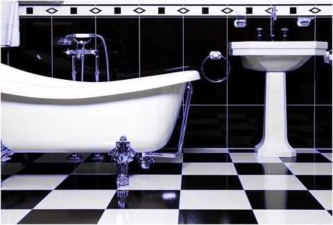
The source/input used in this article is licensed under the Creative Commons Attribution-Share Alike 3.0 Unported license and can be downloaded from Wikipedia: http://en.wikipedia.org/wiki/File:Bathroom_with_bathtube.jpg

Original Image

1280px-Bathroom_with_bathtube

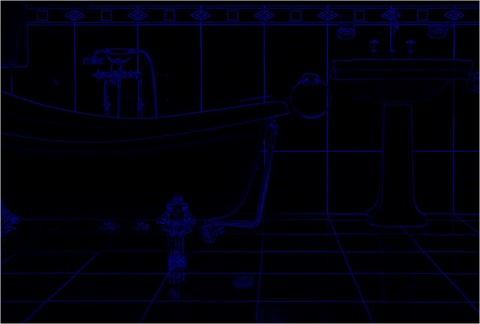
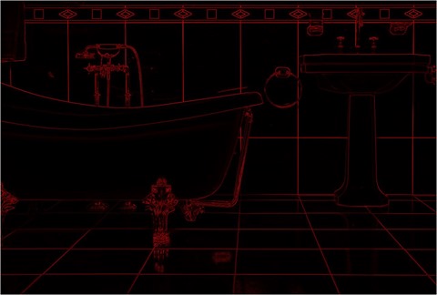
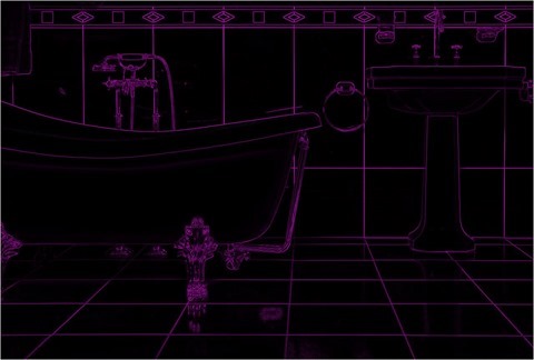
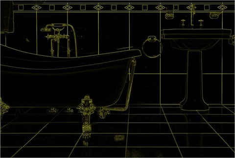
Erosion 3×3, Edge Detect, Red, Green and Blue

Erosion 3x3 Edge Detect Red, Green and Blue

Erosion 3×3, Edge Detect, Blue

Erosion 3x3, Edge Detect, Blue

Erosion 3×3, Edge Detect, Green and Blue

Erosion 3x3, Edge Detect, Green and Blue

Erosion 3×3, Edge Detect, Red

Erosion 3x3, Edge Detect, Red

Erosion 3×3, Edge Detect, Red and Blue

Erosion 3x3, Edge Detect, Red and Blue

Erosion 3×3, Edge Detect, Red and Green

Erosion 3x3, Edge Detect, Red and Green

Erosion 7×7, Sharpen, Red, Green and Blue

Erosion 7x7, Sharpen, Red, Green and Blue

Erosion 7×7, Sharpen, Blue

Erosion 7x7, Sharpen, Blue

Erosion 7×7, Sharpen, Green

Erosion 7x7, Sharpen, Green

Erosion 7×7, Sharpen, Green and Blue

Erosion 7x7, Sharpen, Green and Blue

Erosion 7×7, Sharpen, Red

Erosion 7x7, Sharpen, Red

Erosion 7×7, Sharpen, Red and Blue

Erosion 7x7, Sharpen, Red and Blue

Erosion 7×7, Sharpen, Red and Green

Erosion 7x7, Sharpen, Red and Green

Related Articles and Feedback

Feedback and questions are always encouraged. If you know of an alternative implementation or have ideas on a more efficient implementation please share in the comments section.

I’ve published a number of articles related to imaging and images of which you can find URL links here:

C# How to: Image Erosion and Dilation

Article purpose

The purpose of this article is aimed at exploring the concepts of , , and . In addition this article extends conventional and implementations through partial colour variations of and .

Sample source code

This article is accompanied by a sample source code Visual Studio project which is available for download .

Using the sample application

Included in this article’s sample source code you’ll find a based sample application. The sample application can be used to test and replicate the concepts we explore in this article.

When executing the sample application source/input can selected from the local system by clicking the Load Image button. On the right-hand side of the sample application’s user interface users can adjust the provided controls in order to modify the method of filtering being implemented.

The three labelled Red, Green and Blue relate to whether the relevant colour component will be regarded or not when implementing the configured filter.

Users are required to select an filter: , or . The interface selection is expressed by means of four respectively labelled Dilate, Erode, Open and Closed.

The only other input required from a user comes in the form of selecting the filter intensity/filter size. The dropdown indicated as Filter Size provides the user with several intensity levels ranging from 3×3 to 17×17. Note: Larger filter sizes result in additional processing required when implementing the filter. Large set to implement large sized filters may require more processor cycles.

Resulting filtered can be saved to the local file system by clicking the Save Image button. The screenshot below illustrates the Image Erosion and Dilation sample application in action:

Image_Erosion_Dilation_Sample_Application

Mathematical Morphology

A description of as expressed on :

Mathematical morphology (MM) is a theory and technique for the analysis and processing of geometrical structures, based on , , , and . MM is most commonly applied to , but it can be employed as well on , , , and many other spatial structures.

and -space concepts such as size, , , , and , were introduced by MM on both continuous and . MM is also the foundation of morphological image processing, which consists of a set of operators that transform images according to the above characterizations.

MM was originally developed for , and was later extended to and images. The subsequent generalization to is widely accepted today as MM’s theoretical foundation.

In this article we explore , , as well as and . The implementation of these filters are significantly easier to grasp when compared to most definitions of .

Image Erosion and Dilation

and are implementations of , a subset of . In simpler terms can be defined by this :

Dilation is one of the two basic operators in the area of , the other being . It is typically applied to , but there are versions that work on . The basic effect of the operator on a binary image is to gradually enlarge the boundaries of regions of foreground (i.e. white pixels, typically). Thus areas of foreground pixels grow in size while holes within those regions become smaller.

being a related concept is defined by this :

Erosion is one of the two basic operators in the area of mathematical morphology, the other being . It is typically applied to binary images, but there are versions that work on . The basic effect of the operator on a binary image is to erode away the boundaries of regions of foreground (i.e. white pixels, typically). Thus areas of foreground pixels shrink in size, and holes within those areas become larger.

From the definitions listed above we gather that increases the size of edges contained in an image. In contrast decreases or shrinks the size of an Image’s edges.

Open and Closed Morphology

Building upon the concepts of and this section explores and . A good definition of can be expressed as :

The basic effect of an opening is somewhat like erosion in that it tends to remove some of the foreground (bright) pixels from the edges of regions of foreground pixels. However it is less destructive than erosion in general. As with other morphological operators, the exact operation is determined by a . The effect of the operator is to preserve foreground regions that have a similar shape to this structuring element, or that can completely contain the structuring element, while eliminating all other regions of foreground pixels.

In turn can be defined as :

Closing is similar in some ways to dilation in that it tends to enlarge the boundaries of foreground (bright) regions in an image (and shrink background color holes in such regions), but it is less destructive of the original boundary shape. As with other , the exact operation is determined by a . The effect of the operator is to preserve background regions that have a similar shape to this structuring element, or that can completely contain the structuring element, while eliminating all other regions of background pixels.

Implementing Image Erosion and Dilation

In this article we implement and by iterating each pixel contained within an image. The colour of each pixel is determined by taking into regard a pixel’s neighbouring pixels.

When implementing a pixel’s value is determined by comparing neighbouring pixels’ colour values, determining the highest colour value expressed amongst neighbouring pixels.

In contrast to we implement by also inspecting neighbouring pixels’ colour values, determining the lowest colour value expressed amongst neighbouring pixels.

In addition to conventional and the sample source code provides the ability to perform  and targeting only specific colour components. The result of specific colour and produces images which express the effects of and only in certain colours. Depending on filter parameters specified edges appear to have a coloured glow or shadow.

The sample source code provides the definition for the DilateAndErodeFilter , targeting the class. The following code snippet details the implementation of the DilateAndErodeFilter :

public static Bitmap DilateAndErodeFilter(
                           this Bitmap sourceBitmap,  
                           int matrixSize, 
                           MorphologyType morphType, 
                           bool applyBlue = true, 
                           bool applyGreen = true, 
                           bool applyRed = true )  
{
    BitmapData sourceData =  
               sourceBitmap.LockBits(new Rectangle (0, 0, 
               sourceBitmap.Width, sourceBitmap.Height), 
               ImageLockMode.ReadOnly,  
               PixelFormat.Format32bppArgb); 

byte[] pixelBuffer = new byte[sourceData.Stride * sourceData.Height];
byte[] resultBuffer = new byte[sourceData.Stride * sourceData.Height];
Marshal.Copy(sourceData.Scan0, pixelBuffer, 0, pixelBuffer.Length);
sourceBitmap.UnlockBits(sourceData);
int filterOffset = (matrixSize - 1) / 2; int calcOffset = 0;
int byteOffset = 0;
byte blue = 0; byte green = 0; byte red = 0;
byte morphResetValue = 0;
if (morphType == MorphologyType.Erosion) { morphResetValue = 255; }
for (int offsetY = filterOffset; offsetY < sourceBitmap.Height - filterOffset; offsetY++) { for (int offsetX = filterOffset; offsetX < sourceBitmap.Width - filterOffset; offsetX++) { byteOffset = offsetY * sourceData.Stride + offsetX * 4;
blue = morphResetValue; green = morphResetValue; red = morphResetValue;
if (morphType == MorphologyType.Dilation) { for (int filterY = -filterOffset; filterY <= filterOffset; filterY++) { for (int filterX = -filterOffset; filterX <= filterOffset; filterX++) { calcOffset = byteOffset + (filterX * 4) + (filterY * sourceData.Stride);
if (pixelBuffer[calcOffset] > blue) { blue = pixelBuffer[calcOffset]; }
if (pixelBuffer[calcOffset + 1] > green) { green = pixelBuffer[calcOffset + 1]; }
if (pixelBuffer[calcOffset + 2] > red) { red = pixelBuffer[calcOffset + 2]; } } } } else if (morphType == MorphologyType .Erosion) { for (int filterY = -filterOffset; filterY <= filterOffset; filterY++) { for (int filterX = -filterOffset; filterX <= filterOffset; filterX++) { calcOffset = byteOffset + (filterX * 4) + (filterY * sourceData.Stride);
if (pixelBuffer[calcOffset] < blue) { blue = pixelBuffer[calcOffset]; }
if (pixelBuffer[calcOffset + 1] < green) { green = pixelBuffer[calcOffset + 1]; }
if (pixelBuffer[calcOffset + 2] < red) { red = pixelBuffer[calcOffset + 2]; } } } }
if (applyBlue == false ) { blue = pixelBuffer[byteOffset]; }
if (applyGreen == false ) { green = pixelBuffer[byteOffset + 1]; }
if (applyRed == false ) { red = pixelBuffer[byteOffset + 2]; }
resultBuffer[byteOffset] = blue; resultBuffer[byteOffset + 1] = green; resultBuffer[byteOffset + 2] = red; resultBuffer[byteOffset + 3] = 255; } }
Bitmap resultBitmap = new Bitmap (sourceBitmap.Width, sourceBitmap.Height);
BitmapData resultData = resultBitmap.LockBits(new Rectangle (0, 0, resultBitmap.Width, resultBitmap.Height), ImageLockMode.WriteOnly, PixelFormat.Format32bppArgb);
Marshal.Copy(resultBuffer, 0, resultData.Scan0, resultBuffer.Length);
resultBitmap.UnlockBits(resultData);
return resultBitmap; }

Implementing Open and Closed Morphology

The sample source code implements by first implementing on a source image, the resulting image is then filtered by implementing .

In a reverse fashion is achieved by first implementing on a source image, which is then further filtered by implementing .

The sample source code defines the OpenMorphologyFilter and CloseMorphologyFilter , both targeting the class. The implementation as follows:

public static Bitmap OpenMorphologyFilter(
                            this Bitmap sourceBitmap, 
                            int matrixSize,
                            bool applyBlue = true, 
                            bool applyGreen = true, 
                            bool applyRed = true ) 
{ 
    Bitmap resultBitmap = 
           sourceBitmap.DilateAndErodeFilter(
                        matrixSize, MorphologyType.Erosion, 
                        applyBlue, applyGreen, applyRed); 

resultBitmap = resultBitmap.DilateAndErodeFilter( matrixSize, MorphologyType.Dilation, applyBlue, applyGreen, applyRed);
return resultBitmap; }
public static Bitmap CloseMorphologyFilter( this Bitmap sourceBitmap, int matrixSize, bool applyBlue = true, bool applyGreen = true, bool applyRed = true ) { Bitmap resultBitmap = sourceBitmap.DilateAndErodeFilter( matrixSize, MorphologyType.Dilation, applyBlue, applyGreen, applyRed);
resultBitmap = resultBitmap.DilateAndErodeFilter( matrixSize, MorphologyType.Erosion, applyBlue, applyGreen, applyRed);
return resultBitmap; }

Sample Images

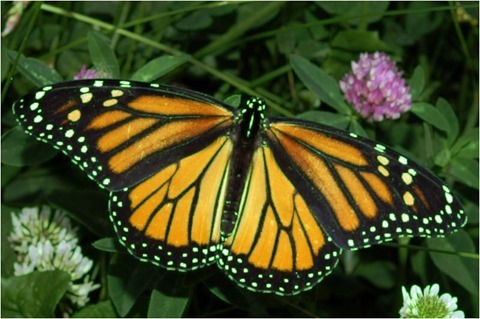
The original source image used to create all of the sample images in this article has been licensed under the Creative Commons Attribution-Share Alike 3.0 Unported, 2.5 Generic, 2.0 Generic and 1.0 Generic license. The original image is attributed to Kenneth Dwain Harrelson and can be downloaded from .

The Original Image

Monarch_In_May

Image Dilation 3×3 Blue

Image Dilation 3x3 Blue

Image Dilation 3×3 Blue, Green

Image Dilation 3x3 Blue, Green

Image Dilation 3×3 Green

Image Dilation 3x3 Green

Image Dilation 3×3 Red

Image Dilation 3x3 Red

Image Dilation 3×3 Red, Blue

Image Dilation 3x3 Red, Blue

Image Dilation 3×3 Red, Green, Blue

Image Dilation 3x3 Red, Green, Blue

Image Dilation 13×13 Blue

Image Dilation 13x13 Blue

Image Erosion 3×3 Green, Blue

Image Erosion 3x3 Green, Blue

Image Erosion 3×3 Green

Image Erosion 3x3 Green

Image Erosion 3×3 Red

Image Erosion 3x3 Red

Image Erosion 3×3 Red, Blue

Image Erosion 3x3 Red, Blue

Image Erosion 3×3 Red, Green

Image Erosion 3x3 Red, Green

Image Erosion 3×3 Red, Green, Blue

Image Erosion 3x3 Red, Green, Blue

Image Erosion 9×9 Green

Image Erosion 9x9 Green

Image Erosion 9×9 Red

Image Erosion 9x9 Red

Image Open Morphology 11×11 Green

Image Open Morphology 11x11 Green

Image Open Morphology 11×11 Green Blue

Image Open Morphology 11x11 Green Blue

Image Open Morphology 11×11 Red

Image Open Morphology 11x11 Red

Image Open Morphology 11×11 Red, Blue

Image Open Morphology 11x11 Red, Blue

Related Articles and Feedback

Feedback and questions are always encouraged. If you know of an alternative implementation or have ideas on a more efficient implementation please share in the comments section.

I’ve published a number of articles related to imaging and images of which you can find URL links here:

C# How to: Image Colour Average

Article purpose

This article’s intension is focussed on providing a discussion on the tasks involved in implementing Image Colour Averaging. Pixel colour averages are calculated from neighbouring pixels.

Sample source code

This article is accompanied by a sample source code Visual Studio project which is available for download .

Using the Sample Application

The sample source code associated with this article includes a based sample application. The sample application is provided with the intention of illustrating the concepts explored in this article. In addition the sample application serves as a means of testing and replicating results.

By clicking the Load Image button users are able to select input/source from the local system. On the right hand side of the screen various controls enable the user to control the implementation of colour averaging. The three labelled Red, Green and Blue relates to whether an individual colour component is to be included in calculating colour averages.

The filter intensity can be specified through selecting a filter size from the dropdown , specifying higher values will result in output images expressing more colour averaging intensity.

Additional image filter effects can be achieved through implementing colour component shifting/swapping. When colour components are shifted left the result will be:

  • Blue is set to the original value of the Red component.
  • Red is set to the original value of the Green component.
  • Green is set to the original value of the Blue component.

When colour components are shifted right the result will be:

  • Red is set to the original value of the Blue component
  • Blue is set to the original value of the Green component
  • Green is set to the original value of the Red Component

Resulting can be saved by the user to the local file system by clicking the Save Image button. The following image is a screenshot of the Image Colour Average sample application in action:

Image Colour Average Sample Application

Averaging Colours

In this article and the accompanying sample source code colour averaging is implemented on a per pixel basis. An average colour value is calculated based on a pixel’s neighbouring pixels’ colour. Determining neighbouring pixels in the sample source code has been implemented in much the same method as . The major difference to is the absence of a fixed /.

Additional resulting visual effects can be achieved through various options/settings implemented whilst calculating colour averages. Additional options include being able to specify which colour component averages to implement. Furthermore colour components can be swapped/shifted around.

The sample source code implements the AverageColoursFilter , targeting the class. The extent or degree to which colour averaging will be evident in resulting can be controlled through specifying different values set to the matrixSize parameter. The matrixSize parameter in essence determines the number of neighbouring pixels involved in calculating an average colour.

The individual pixel colour components Red, Green and Blue can either be included or excluded in calculating averages. The three method boolean parameters applyBlue, applyGreen and applyRed will determine an individual colour components inclusion in averaging calculations. If a colour component is to be excluded from averaging the resulting will instead express the original source/input image’s colour component.

The intensity of a specific colour component average can be applied to another colour component by means of swapping/shifting colour components, which is indicated through the shiftType method parameter.

The following code snippet provides the implementation of the AverageColoursFilter :

public static Bitmap AverageColoursFilter(
                            this Bitmap sourceBitmap,  
                            int matrixSize,   
                            bool applyBlue = true, 
                            bool applyGreen = true, 
                            bool applyRed = true, 
                            ColorShiftType shiftType = 
                            ColorShiftType.None)  
{ 
    BitmapData sourceData =  
               sourceBitmap.LockBits(new Rectangle(0, 0, 
               sourceBitmap.Width, sourceBitmap.Height), 
               ImageLockMode.ReadOnly,  
               PixelFormat.Format32bppArgb); 

byte[] pixelBuffer = new byte[sourceData.Stride * sourceData.Height];
byte[] resultBuffer = new byte[sourceData.Stride * sourceData.Height];
Marshal.Copy(sourceData.Scan0, pixelBuffer, 0, pixelBuffer.Length);
sourceBitmap.UnlockBits(sourceData);
int filterOffset = (matrixSize - 1) / 2; int calcOffset = 0;
int byteOffset = 0;
int blue = 0; int green = 0; int red = 0;
for (int offsetY = filterOffset; offsetY < sourceBitmap.Height - filterOffset; offsetY++) { for (int offsetX = filterOffset; offsetX < sourceBitmap.Width - filterOffset; offsetX++) { byteOffset = offsetY * sourceData.Stride + offsetX * 4;
blue = 0; green = 0; red = 0;
for (int filterY = -filterOffset; filterY <= filterOffset; filterY++) { for (int filterX = -filterOffset; filterX <= filterOffset; filterX++) { calcOffset = byteOffset + (filterX * 4) + (filterY * sourceData.Stride);
blue += pixelBuffer[calcOffset]; green += pixelBuffer[calcOffset + 1]; red += pixelBuffer[calcOffset + 2]; } }
blue = blue / matrixSize; green = green / matrixSize; red = red / matrixSize;
if (applyBlue == false) { blue = pixelBuffer[byteOffset]; }
if (applyGreen == false) { green = pixelBuffer[byteOffset + 1]; }
if (applyRed == false) { red = pixelBuffer[byteOffset + 2]; }
if (shiftType == ColorShiftType.None) { resultBuffer[byteOffset] = (byte)blue; resultBuffer[byteOffset + 1] = (byte)green; resultBuffer[byteOffset + 2] = (byte)red; resultBuffer[byteOffset + 3] = 255; } else if (shiftType == ColorShiftType.ShiftLeft) { resultBuffer[byteOffset] = (byte)green; resultBuffer[byteOffset + 1] = (byte)red; resultBuffer[byteOffset + 2] = (byte)blue; resultBuffer[byteOffset + 3] = 255; } else if (shiftType == ColorShiftType.ShiftRight) { resultBuffer[byteOffset] = (byte)red; resultBuffer[byteOffset + 1] = (byte)blue; resultBuffer[byteOffset + 2] = (byte)green; resultBuffer[byteOffset + 3] = 255; } } }
Bitmap resultBitmap = new Bitmap(sourceBitmap.Width, sourceBitmap.Height);
BitmapData resultData = resultBitmap.LockBits(new Rectangle(0, 0, resultBitmap.Width, resultBitmap.Height), ImageLockMode.WriteOnly, PixelFormat.Format32bppArgb);
Marshal.Copy(resultBuffer, 0, resultData.Scan0, resultBuffer.Length);
resultBitmap.UnlockBits(resultData);
return resultBitmap; }

The definition of the ColorShiftType :

public enum ColorShiftType  
{
    None, 
    ShiftLeft, 
    ShiftRight 
}

Sample

The original image used in generating the sample images that form part of this article, has been licensed under the Attribution-Share Alike , , and license. The can be from .

Original Image

Rose_Amber_Flush_20070601

Colour Average Blue Size 11

Colour Average Blue Size 11

Colour Average Blue Size 11 Shift Left

Colour Average Blue Size 11 Shift Left

Colour Average Blue Size 11 Shift Right

Colour Average Blue Size 11 Shift Right

Colour Average Green Size 11 Shift Right

Colour Average Green Size 11 Shift Right

Colour Average Green, Blue Size 11

Colour Average Green, Blue Size 11

Colour Average Green, Blue Size 11 Shift Left

Colour Average Green, Blue Size 11 Shift Left

Colour Average Green, Blue Size 11 Shift Right

Colour Average Green, Blue Size 11 Shift Right

Colour Average Red Size 11

Colour Average Red Size 11

Colour Average Red Size 11 Shift Left

Colour Average Red Size 11 Shift Left

Colour Average Red, Blue Size 11

Colour Average Red, Blue Size 11

Colour Average Red, Blue Size 11 Shift Left

Colour Average Red, Blue Size 11 Shift Left

Colour Average Red, Green Size 11

Colour Average Red, Green Size 11

Colour Average Red, Green Size 11 Shift Left

Colour Average Red, Green Size 11 Shift Left

Colour Average Red, Green Size 11 Shift Right

Colour Average Red, Green Size 11 Shift Right

Colour Average Red, Green, Blue Size 11

Colour Average Red, Green, Blue Size 11

Colour Average Red, Green, Blue Size 11 Shift Left

Colour Average Red, Green, Blue Size 11 Shift Left

Colour Average Red, Green, Blue Size 11 Shift Right

Colour Average Red, Green, Blue Size 11 Shift Right

Related Articles and Feedback

Feedback and questions are always encouraged. If you know of an alternative implementation or have ideas on a more efficient implementation please share in the comments section.

I’ve published a number of articles related to imaging and images of which you can find URL links here:

C# How to: Image Unsharp Mask

Article purpose

The purpose of this article is to explore and illustrate the concept of . This article implements in the form of a 3×3 , 5×5 , 3×3 Mean filter and a 5×5 Mean filter.

Sample Source code

This article is accompanied by a sample source code Visual Studio project which is available for download .

Using the Sample Application

The sample source code associated with this article includes a based sample application implementing the concepts explored throughout this article.

When using the Image Unsharp Mask sample application users can select a source/input image from the local system by clicking the Load Image button. The dropdown at the bottom of the screen allows the user to select an unsharp masking variation. On the right hand side of the screen users can specify the level/intensity of resulting .

Clicking the Save Image button allows a user to save resulting to the local file system. The image below is a screenshot of the Image Unsharp Mask sample application in action:

Image Unsharp Mask Sample Application

What is Image Unsharp Masking?

A good definition of can be found on :

Unsharp masking (USM) is an image manipulation technique, often available in software.

The "unsharp" of the name derives from the fact that the technique uses a blurred, or "unsharp", positive image to create a "mask" of the original image. The unsharped mask is then combined with the negative image, creating an image that is less blurry than the original. The resulting image, although clearer, probably loses accuracy with respect to the image’s subject. In the context of , an unsharp mask is generally a or filter that amplifies high-frequency components.

In this article we implement by first creating a blurred copy of a source/input then subtracting the blurred from the original , which is known as the mask. Increased is achieved by adding a factor of the mask to the original .

Applying a Convolution Matrix filter

The sample source code provides the definition for the ConvolutionFilter targeting the class. method is invoked when implementing . The definition of the ConvolutionFilter as follows:

 private static Bitmap ConvolutionFilter(Bitmap sourceBitmap,  
                                     double[,] filterMatrix,  
                                          double factor = 1,  
                                               int bias = 0,  
                                     bool grayscale = false )  
{ 
     BitmapData sourceData = sourceBitmap.LockBits(new Rectangle (0, 0, 
                              sourceBitmap.Width, sourceBitmap.Height), 
                                                ImageLockMode.ReadOnly,  
                                          PixelFormat.Format32bppArgb); 

byte[] pixelBuffer = new byte[sourceData.Stride * sourceData.Height]; byte[] resultBuffer = new byte[sourceData.Stride * sourceData.Height];
Marshal.Copy(sourceData.Scan0, pixelBuffer, 0, pixelBuffer.Length); sourceBitmap.UnlockBits(sourceData);
if (grayscale == true) { float rgb = 0;
for (int k = 0; k < pixelBuffer.Length; k += 4) { rgb = pixelBuffer[k] * 0.11f; rgb += pixelBuffer[k + 1] * 0.59f; rgb += pixelBuffer[k + 2] * 0.3f;
pixelBuffer[k] = (byte )rgb; pixelBuffer[k + 1] = pixelBuffer[k]; pixelBuffer[k + 2] = pixelBuffer[k]; pixelBuffer[k + 3] = 255; } }
double blue = 0.0; double green = 0.0; double red = 0.0;
int filterWidth = filterMatrix.GetLength(1); int filterHeight = filterMatrix.GetLength(0);
int filterOffset = (filterWidth-1) / 2; int calcOffset = 0;
int byteOffset = 0;
for (int offsetY = filterOffset; offsetY < sourceBitmap.Height - filterOffset; offsetY++) { for (int offsetX = filterOffset; offsetX < sourceBitmap.Width - filterOffset; offsetX++) { blue = 0; green = 0; red = 0;
byteOffset = offsetY * sourceData.Stride + offsetX * 4;
for (int filterY = -filterOffset; filterY <= filterOffset; filterY++) { for (int filterX = -filterOffset; filterX <= filterOffset; filterX++) {
calcOffset = byteOffset + (filterX * 4) + (filterY * sourceData.Stride);
blue += (double)(pixelBuffer[calcOffset]) * filterMatrix[filterY + filterOffset, filterX + filterOffset];
green += (double)(pixelBuffer[calcOffset + 1]) * filterMatrix[filterY + filterOffset, filterX + filterOffset];
red += (double)(pixelBuffer[calcOffset + 2]) * filterMatrix[filterY + filterOffset, filterX + filterOffset]; } }
blue = factor * blue + bias; green = factor * green + bias; red = factor * red + bias;
if (blue > 255) { blue = 255; } else if (blue < 0) { blue = 0; }
if (green > 255) { green = 255; } else if (green < 0) { green = 0; }
if (red > 255) { red = 255; } else if (red < 0) { red = 0; }
resultBuffer[byteOffset] = (byte )(blue); resultBuffer[byteOffset + 1] = (byte )(green); resultBuffer[byteOffset + 2] = (byte )(red); resultBuffer[byteOffset + 3] = 255; } }
Bitmap resultBitmap = new Bitmap(sourceBitmap.Width, sourceBitmap.Height); BitmapData resultData = resultBitmap.LockBits(new Rectangle (0, 0, resultBitmap.Width, resultBitmap.Height), ImageLockMode.WriteOnly, PixelFormat.Format32bppArgb);
Marshal.Copy(resultBuffer, 0, resultData.Scan0, resultBuffer.Length); resultBitmap.UnlockBits(resultData);
return resultBitmap; }

Subtracting and Adding Images

An important step required when implementing comes in the form of creating a mask by subtracting a blurred copy from the original and then adding a factor of the mask to the original . In order to achieve increased performance the sample source code combines the process of creating the mask and adding the mask to the original .

The SubtractAddFactorImage iterates every pixel that forms part of an . In a single step the blurred pixel is subtracted from the original pixel, multiplied by a user specified factor and then added to the original pixel. The definition of the SubtractAddFactorImage as follows:

private static Bitmap SubtractAddFactorImage( 
                              this Bitmap subtractFrom, 
                                  Bitmap subtractValue, 
                                   float factor = 1.0f) 
{ 
    BitmapData sourceData =  
               subtractFrom.LockBits(new Rectangle (0, 0, 
               subtractFrom.Width, subtractFrom.Height), 
               ImageLockMode.ReadOnly, 
               PixelFormat.Format32bppArgb); 

byte[] sourceBuffer = new byte[sourceData.Stride * sourceData.Height];
Marshal.Copy(sourceData.Scan0, sourceBuffer, 0, sourceBuffer.Length);
byte[] resultBuffer = new byte[sourceData.Stride * sourceData.Height];
BitmapData subtractData = subtractValue.LockBits(new Rectangle (0, 0, subtractValue.Width, subtractValue.Height), ImageLockMode.ReadOnly, PixelFormat.Format32bppArgb);
byte[] subtractBuffer = new byte[subtractData.Stride * subtractData.Height];
Marshal.Copy(subtractData.Scan0, subtractBuffer, 0, subtractBuffer.Length);
subtractFrom.UnlockBits(sourceData); subtractValue.UnlockBits(subtractData);
double blue = 0; double green = 0; double red = 0;
for (int k = 0; k < resultBuffer.Length && k < subtractBuffer.Length; k += 4) { blue = sourceBuffer[k] + (sourceBuffer[k] - subtractBuffer[k]) * factor;
green = sourceBuffer[k + 1] + (sourceBuffer[k + 1] - subtractBuffer[k + 1]) * factor;
red = sourceBuffer[k + 2] + (sourceBuffer[k + 2] - subtractBuffer[k + 2]) * factor;
blue = (blue < 0 ? 0 : (blue > 255 ? 255 : blue)); green = (green < 0 ? 0 : (green > 255 ? 255 : green)); red = (red < 0 ? 0 : (red > 255 ? 255 : red));
resultBuffer[k] = (byte )blue; resultBuffer[k + 1] = (byte )green; resultBuffer[k + 2] = (byte )red; resultBuffer[k + 3] = 255; }
Bitmap resultBitmap = new Bitmap (subtractFrom.Width, subtractFrom.Height);
BitmapData resultData = resultBitmap.LockBits(new Rectangle (0, 0, resultBitmap.Width, resultBitmap.Height), ImageLockMode.WriteOnly, PixelFormat.Format32bppArgb);
Marshal.Copy(resultBuffer, 0, resultData.Scan0, resultBuffer.Length);
resultBitmap.UnlockBits(resultData);
return resultBitmap; }

Matrix Definition

The image blurring filters implemented by the sample source code relies on static / values defined in the Matrix class. The variants of implemented are: 3×3 , 5×5 Gaussian, 3×3 Mean and 5×5 Mean. The definition of the Matrix class is detailed by the following code snippet:

public static class Matrix
{
    public static double[,] Gaussian3x3
    {
        get
        {
            return new double[,]
            { { 1, 2, 1, }, 
              { 2, 4, 2, }, 
              { 1, 2, 1, }, };
        }
    }

public static double[,] Gaussian5x5Type1 { get { return new double[,] { { 2, 04, 05, 04, 2 }, { 4, 09, 12, 09, 4 }, { 5, 12, 15, 12, 5 }, { 4, 09, 12, 09, 4 }, { 2, 04, 05, 04, 2 }, }; } }
public static double[,] Mean3x3 { get { return new double[,] { { 1, 1, 1, }, { 1, 1, 1, }, { 1, 1, 1, }, }; } }
public static double[,] Mean5x5 { get { return new double[,] { { 1, 1, 1, 1, 1 }, { 1, 1, 1, 1, 1 }, { 1, 1, 1, 1, 1 }, { 1, 1, 1, 1, 1 }, { 1, 1, 1, 1, 1 }, }; } } }

Implementing Image Unsharpening

This article explores four variants of , relating to the four types of image blurring discussed in the previous section. The sample source code defines the following : UnsharpGaussian3x3, UnsharpGaussian5x5, UnsharpMean3x3 and UnsharpMean5x5. All four methods are defined as targeting the class. When looking at the sample images in the following section you will notice the correlation between increased and enhanced . The definition as follows:

public static Bitmap UnsharpGaussian3x3( 
                                 this Bitmap sourceBitmap,  
                                 float factor = 1.0f) 
{
    Bitmap blurBitmap = ExtBitmap.ConvolutionFilter( 
                                  sourceBitmap,  
                                  Matrix.Gaussian3x3,  
                                  1.0 / 16.0); 

Bitmap resultBitmap = sourceBitmap.SubtractAddFactorImage( blurBitmap, factor);
return resultBitmap; }
public static Bitmap UnsharpGaussian5x5( this Bitmap sourceBitmap, float factor = 1.0f) { Bitmap blurBitmap = ExtBitmap.ConvolutionFilter( sourceBitmap, Matrix.Gaussian5x5Type1, 1.0 / 159.0);
Bitmap resultBitmap = sourceBitmap.SubtractAddFactorImage( blurBitmap, factor);
return resultBitmap; } public static Bitmap UnsharpMean3x3( this Bitmap sourceBitmap, float factor = 1.0f) { Bitmap blurBitmap = ExtBitmap.ConvolutionFilter( sourceBitmap, Matrix.Mean3x3, 1.0 / 9.0);
Bitmap resultBitmap = sourceBitmap.SubtractAddFactorImage( blurBitmap, factor);
return resultBitmap; }
public static Bitmap UnsharpMean5x5( this Bitmap sourceBitmap, float factor = 1.0f) { Bitmap blurBitmap = ExtBitmap.ConvolutionFilter( sourceBitmap, Matrix.Mean5x5, 1.0 / 25.0);
Bitmap resultBitmap = sourceBitmap.SubtractAddFactorImage( blurBitmap, factor);
return resultBitmap; }

Sample Images

The used in rendering the sample images shown in this article is licensed under the Creative Commons Attribution-Share Alike 3.0 Unported license and can be from :

The Original Image

W-A-S-D

Unsharp Gaussian 3×3

Unsharp Gaussian 3x3

Unsharp Gaussian 5×5

Unsharp Gaussian 5x5

Unsharp Mean 3×3

Unsharp Mean 3x3

Unsharp Gaussian 5×5

Unsharp Mean 5x5

Related Articles and Feedback

Feedback and questions are always encouraged. If you know of an alternative implementation or have ideas on a more efficient implementation please share in the comments section.

I’ve published a number of articles related to imaging and images of which you can find URL links here:

C# How to: Image Median Filter

Article purpose

The objective of this article is focussed on providing a discussion on implementing a on an . This article illustrates varying levels of filter intensity: 3×3, 5×5, 7×7, 9×9, 11×11 and 13×13.

Sample source code

This article is accompanied by a sample source code Visual Studio project which is available for download .

Using the Sample Application

The concepts explored in this article can be easily replicated by making use of the Sample Application, which forms part of the associated sample source code accompanying this article.

When using the Image Median Filter sample application you can specify a input/source image by clicking the Load Image button. The dropdown combobox towards the bottom middle part of the screen relates the various levels of filter intensity.

If desired a user can save the resulting filtered image to the local file system by clicking the Save Image button.

The following image is screenshot of the Image Median Filter sample application in action:

Image Median Filter Sample Application

What is a Median Filter

From we gain the following :

In , it is often desirable to be able to perform some kind of noise reduction on an image or signal. The median filter is a nonlinear technique, often used to remove noise. Such noise reduction is a typical pre-processing step to improve the results of later processing (for example, on an image). Median filtering is very widely used in digital because, under certain conditions, it preserves edges while removing noise (but see discussion below).

The main idea of the median filter is to run through the signal entry by entry, replacing each entry with the of neighboring entries. The pattern of neighbors is called the "window", which slides, entry by entry, over the entire signal. For 1D signals, the most obvious window is just the first few preceding and following entries, whereas for 2D (or higher-dimensional) signals such as images, more complex window patterns are possible (such as "box" or "cross" patterns). Note that if the window has an odd number of entries, then the is simple to define: it is just the middle value after all the entries in the window are sorted numerically. For an even number of entries, there is more than one possible median, see for more details.

In simple terms, a can be applied to in order to achieve smoothing or reduction. The in contrast to most smoothing methods, to a degree exhibits edge preservation properties.

Applying a Median Filter

The sample source code defines the MedianFilter targeting the class. The matrixSize parameter determines the intensity of the being applied.

The MedianFilter iterates each pixel of the source . When iterating pixels we determine the neighbouring pixels of the pixel currently being iterated. After having built up a list of neighbouring pixels, the List is then sorted and from there we determine the middle pixel value. The final step involves assigning the determined middle pixel to the current pixel in the resulting , represented as an array of pixel colour component .

public static Bitmap MedianFilter(this Bitmap sourceBitmap,  
                                            int matrixSize,   
                                              int bias = 0,  
                                    bool grayscale = false)  
{
    BitmapData sourceData =  
               sourceBitmap.LockBits(new Rectangle (0, 0, 
               sourceBitmap.Width, sourceBitmap.Height), 
               ImageLockMode.ReadOnly,  
               PixelFormat.Format32bppArgb); 

byte[] pixelBuffer = new byte[sourceData.Stride * sourceData.Height];
byte[] resultBuffer = new byte[sourceData.Stride * sourceData.Height];
Marshal.Copy(sourceData.Scan0, pixelBuffer, 0, pixelBuffer.Length);
sourceBitmap.UnlockBits(sourceData);
if (grayscale == true) { float rgb = 0;
for (int k = 0; k < pixelBuffer.Length; k += 4) { rgb = pixelBuffer[k] * 0.11f; rgb += pixelBuffer[k + 1] * 0.59f; rgb += pixelBuffer[k + 2] * 0.3f;
pixelBuffer[k] = (byte )rgb; pixelBuffer[k + 1] = pixelBuffer[k]; pixelBuffer[k + 2] = pixelBuffer[k]; pixelBuffer[k + 3] = 255; } }
int filterOffset = (matrixSize - 1) / 2; int calcOffset = 0;
int byteOffset = 0; List<int> neighbourPixels = new List<int>(); byte[] middlePixel;
for (int offsetY = filterOffset; offsetY < sourceBitmap.Height - filterOffset; offsetY++) { for (int offsetX = filterOffset; offsetX < sourceBitmap.Width - filterOffset; offsetX++) { byteOffset = offsetY * sourceData.Stride + offsetX * 4;
neighbourPixels.Clear();
for (int filterY = -filterOffset; filterY <= filterOffset; filterY++) { for (int filterX = -filterOffset; filterX <= filterOffset; filterX++) {
calcOffset = byteOffset + (filterX * 4) + (filterY * sourceData.Stride);
neighbourPixels.Add(BitConverter.ToInt32( pixelBuffer, calcOffset)); } }
neighbourPixels.Sort(); middlePixel = BitConverter.GetBytes( neighbourPixels[filterOffset]);
resultBuffer[byteOffset] = middlePixel[0]; resultBuffer[byteOffset + 1] = middlePixel[1]; resultBuffer[byteOffset + 2] = middlePixel[2]; resultBuffer[byteOffset + 3] = middlePixel[3]; } }
Bitmap resultBitmap = new Bitmap(sourceBitmap.Width, sourceBitmap.Height);
BitmapData resultData = resultBitmap.LockBits(new Rectangle (0, 0, resultBitmap.Width, resultBitmap.Height), ImageLockMode.WriteOnly, PixelFormat.Format32bppArgb);
Marshal.Copy(resultBuffer, 0, resultData.Scan0, resultBuffer.Length);
resultBitmap.UnlockBits(resultData);
return resultBitmap; }

Sample Images

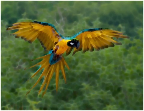
The sample images illustrated in this article were rendered from the same source image which is licensed under the Creative Commons Attribution-Share Alike 3.0 Unported, 2.5 Generic, 2.0 Generic and 1.0 Generic license. The original image is attributed to Luc Viatourwww.Lucnix.be and can be downloaded from Wikipedia.

The Original Source Image

Ara_ararauna_Luc_Viatour

Median 3×3 Filter

Median Filter 3x3

Median 5×5 Filter

Median Filter 5x5

Median 7×7 Filter

Median Filter 7x7

Median 9×9 Filter

Median Filter 9x9

Median 11×11 Filter

Median Filter 11x11

Median 13×13 Filter

Median Filter 13x13

Related Articles and Feedback

Feedback and questions are always encouraged. If you know of an alternative implementation or have ideas on a more efficient implementation please share in the comments section.

I’ve published a number of articles related to imaging and images of which you can find URL links here:


Dewald Esterhuizen

Blog Stats

  • 869,882 hits

Enter your email address to follow and receive notifications of new posts by email.

Join 228 other subscribers

Archives

RSS SoftwareByDefault on MSDN

  • An error has occurred; the feed is probably down. Try again later.