Posts Tagged 'BitmapData.Stride'

C# How to: Compass Edge Detection

Article Purpose

This article’s objective is to illustrate concepts relating to Compass . The methods implemented in this article include: , , Scharr, and Isotropic.

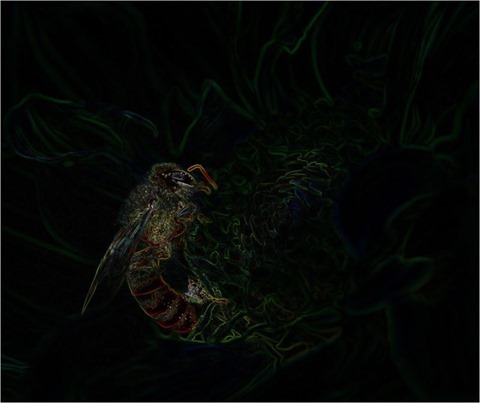
Wasp: Scharr 3 x 3 x 8

Wasp Scharr 3 x 3 x 8

Sample Source Code

This article is accompanied by a sample source code Visual Studio project which is available for download here.

Using the Sample Application

The sample source code accompanying this article includes a based sample application. When using the sample application users are able to load source/input from and save result to the local system. The user interface provides a which contains the supported methods of Compass Edge Detection. Selecting an item from the results in the related Compass Edge Detection method being applied to the current source/input . Supported methods are:

  • Prewitt3x3x4 – 3×3 in 4 compass directions
  • Prewitt3x3x8 – 3×3 in 8 compass directions
  • Prewitt5x5x4 – 5×5 in 4 compass directions
  • Sobel3x3x4 – 3×3 in 4 compass directions
  • Sobel3x3x8 – 3×3 in 8 compass directions
  • Sobel5x5x4 – 5×5 in 4 compass directions
  • Scharr3x3x4 – 3×3 Scharr in 4 compass directions
  • Scharr3x3x8 – 3×3 Scharr in 8 compass directions
  • Scharr5x5x4 – 5×5 Scharr in 4 compass directions
  • Kirsch3x3x4 – 3×3 in 4 compass directions
  • Kirsch3x3x8 – 3×3 in 8 compass directions
  • Isotropic3x3x4 – 3×3 Isotropic in 4 compass directions
  • Isotropic3x3x8 – 3×3 Isotropic in 8 compass directions

The following image is a screenshot of the Compass Edge Detection Sample Application in action:

Compass Edge Detection Sample Application

Bee: Isotropic 3 x 3 x 8

Bee Isotropic 3 x 3 x 8

Compass Edge Detection Overview

Compass Edge Detection as a concept title can be explained through the implementation of compass directions. Compass Edge Detection can be implemented through , using multiple , each suited to detecting edges in a specific direction. Often the edge directions implemented are:

  • North
  • North East
  • East
  • South East
  • South
  • South West
  • West
  • North West

Each of the compass directions listed above differ by 45 degrees. Applying a rotation of 45 degrees to an existing direction specific results in a new suited to detecting edges in the next compass direction.

Various can be implemented in Compass Edge Detection. This article and accompanying sample source code implements the following types:

Prey Mantis: Sobel 3 x 3 x 8

Prey Mantis Sobel 3 x 3 x 8

The steps required when implementing Compass Edge Detection can be described as follows:

  1. Determine the compass kernels. When an   suited to a specific direction is known, the suited to the 7 remaining compass directions can be calculated. Rotating a by 45 degrees around a central axis equates to the suited to the next compass direction. As an example, if the suited to detect edges in a northerly direction were to be rotated clockwise by 45 degrees around a central axis the result would be an suited to edges in a North Easterly direction.
  2. Iterate source image pixels. Every pixel forming part of the source/input should be iterated, implementing using each of the compass .
  3. Determine the most responsive kernel convolution. After having applied each compass to the pixel currently being iterated, the most responsive compass determines the output value. In other words, after having applied eight times on the same pixel using each compass direction the output value should be set to the highest value calculated.
  4. Validate and set output result. Ensure that the highest value returned from does not equate to less than 0 or more than 255. Should a value be less than zero the result should be assigned as zero. In a similar fashion, should a value exceed 255 the result should be assigned as 255.

Prewitt Compass Kernels

Prewitt Compass Kernels

LadyBug: Prewitt 3 x 3 x 8

LadyBug Prewitt 3 x 3 x 8

Rotating Convolution Kernels

can be rotated by implementing a . Repeatedly rotating by 45 degrees results in calculating 8 , each suited to a different direction. The algorithm implemented when performing a can be expressed as follows:

Rotate Horizontal Algorithm

Rotate Horizontal Algorithm

Rotate Vertical Algorithm

Rotate Vertical Algorithm

I’ve published an in-depth article on rotation available here:  

Butterfly: Sobel 3 x 3 x 8

Butterfly Sobel 3 x 3 x 8

Implementing Kernel Rotation

The sample source code defines the RotateMatrix method. This method accepts as parameter a single , defined as a two dimensional array of type double. In addition the method also expects as a parameter the degree to which the specified should be rotated. The definition as follows:

public static double[, ,] RotateMatrix(double[,] baseKernel,  
                                             double degrees) 
{
    double[, ,] kernel = new double[(int )(360 / degrees),  
        baseKernel.GetLength(0), baseKernel.GetLength(1)]; 

int xOffset = baseKernel.GetLength(1) / 2; int yOffset = baseKernel.GetLength(0) / 2;
for (int y = 0; y < baseKernel.GetLength(0); y++) { for (int x = 0; x < baseKernel.GetLength(1); x++) { for (int compass = 0; compass < kernel.GetLength(0); compass++) { double radians = compass * degrees * Math.PI / 180.0;
int resultX = (int)(Math.Round((x - xOffset) * Math.Cos(radians) - (y - yOffset) * Math.Sin(radians)) + xOffset);
int resultY = (int )(Math.Round((x - xOffset) * Math.Sin(radians) + (y - yOffset) * Math.Cos(radians)) + yOffset);
kernel[compass, resultY, resultX] = baseKernel[y, x]; } } }
return kernel; }

Butterfly: Prewitt 3 x 3 x 8

Butterfly Prewitt 3 x 3 x 8

Implementing Compass Edge Detection

The sample source code defines several which are implemented in . The following code snippet provides the of all defined:

public static double[, ,] Prewitt3x3x4 
{
    get 
    {
        double[,] baseKernel = new double[,]  
         { {  -1,  0,  1,  },  
           {  -1,  0,  1,  },  
           {  -1,  0,  1,  }, }; 

double[, ,] kernel = RotateMatrix(baseKernel, 90);
return kernel; } }
public static double[, ,] Prewitt3x3x8 { get { double[,] baseKernel = new double[,] { { -1, 0, 1, }, { -1, 0, 1, }, { -1, 0, 1, }, };
double[, ,] kernel = RotateMatrix(baseKernel, 45);
return kernel; } }
public static double[, ,] Prewitt5x5x4 { get { double[,] baseKernel = new double[,] { { -2, -1, 0, 1, 2, }, { -2, -1, 0, 1, 2, }, { -2, -1, 0, 1, 2, }, { -2, -1, 0, 1, 2, }, { -2, -1, 0, 1, 2, }, };
double[, ,] kernel = RotateMatrix(baseKernel, 90);
return kernel; } }
public static double[, ,] Kirsch3x3x4 { get { double[,] baseKernel = new double[,] { { -3, -3, 5, }, { -3, 0, 5, }, { -3, -3, 5, }, };
double[, ,] kernel = RotateMatrix(baseKernel, 90);
return kernel; } }
public static double[, ,] Kirsch3x3x8 { get { double[,] baseKernel = new double[,] { { -3, -3, 5, }, { -3, 0, 5, }, { -3, -3, 5, }, };
double[, ,] kernel = RotateMatrix(baseKernel, 45);
return kernel; } }
public static double[, ,] Sobel3x3x4 { get { double[,] baseKernel = new double[,] { { -1, 0, 1, }, { -2, 0, 2, }, { -1, 0, 1, }, };
double[, ,] kernel = RotateMatrix(baseKernel, 90);
return kernel; } }
public static double[, ,] Sobel3x3x8 { get { double[,] baseKernel = new double[,] { { -1, 0, 1, }, { -2, 0, 2, }, { -1, 0, 1, }, };
double[, ,] kernel = RotateMatrix(baseKernel, 45);
return kernel; } }
public static double[, ,] Sobel5x5x4 { get { double[,] baseKernel = new double[,] { { -5, -4, 0, 4, 5, }, { -8, -10, 0, 10, 8, }, { -10, -20, 0, 20, 10, }, { -8, -10, 0, 10, 8, }, { -5, -4, 0, 4, 5, }, };
double[, ,] kernel = RotateMatrix(baseKernel, 90);
return kernel; } }
public static double[, ,] Scharr3x3x4 { get { double[,] baseKernel = new double[,] { { -1, 0, 1, }, { -3, 0, 3, }, { -1, 0, 1, }, };
double[, ,] kernel = RotateMatrix(baseKernel, 90);
return kernel; } }
public static double[, ,] Scharr3x3x8 { get { double[,] baseKernel = new double[,] { { -1, 0, 1, }, { -3, 0, 3, }, { -1, 0, 1, }, };
double[, ,] kernel = RotateMatrix(baseKernel, 45);
return kernel; } }
public static double[, ,] Scharr5x5x4 { get { double[,] baseKernel = new double[,] { { -1, -1, 0, 1, 1, }, { -2, -2, 0, 2, 2, }, { -3, -6, 0, 6, 3, }, { -2, -2, 0, 2, 2, }, { -1, -1, 0, 1, 1, }, };
double[, ,] kernel = RotateMatrix(baseKernel, 90);
return kernel; } }
public static double[, ,] Isotropic3x3x4 { get { double[,] baseKernel = new double[,] { { -1, 0, 1, }, { -Math.Sqrt(2), 0, Math.Sqrt(2), }, { -1, 0, 1, }, };
double[, ,] kernel = RotateMatrix(baseKernel, 90);
return kernel; } }
public static double[, ,] Isotropic3x3x8 { get { double[,] baseKernel = new double[,] { { -1, 0, 1, }, { -Math.Sqrt(2), 0, Math.Sqrt(2), }, { -1, 0, 1, }, };
double[, ,] kernel = RotateMatrix(baseKernel, 45);
return kernel; } }

Notice how each property invokes the RotateMatrix method discussed in the previous section.

Butterfly: Scharr 3 x 3 x 8

Butterfly Scharr 3 x 3 x 8

The CompassEdgeDetectionFilter method is defined as an targeting the class. The purpose of this method is to act as a wrapper method encapsulating the technical implementation. The definition as follows:

public static Bitmap CompassEdgeDetectionFilter(this Bitmap sourceBitmap,  
                                    CompassEdgeDetectionType compassType) 
{ 
    Bitmap resultBitmap = null; 

switch (compassType) { case CompassEdgeDetectionType.Sobel3x3x4: { resultBitmap = sourceBitmap.ConvolutionFilter(Matrix.Sobel3x3x4, 1.0 / 4.0); } break; case CompassEdgeDetectionType.Sobel3x3x8: { resultBitmap = sourceBitmap.ConvolutionFilter(Matrix.Sobel3x3x8, 1.0/ 4.0); } break; case CompassEdgeDetectionType.Sobel5x5x4: { resultBitmap = sourceBitmap.ConvolutionFilter(Matrix.Sobel5x5x4, 1.0/ 84.0); } break; case CompassEdgeDetectionType.Prewitt3x3x4: { resultBitmap = sourceBitmap.ConvolutionFilter(Matrix.Prewitt3x3x4, 1.0 / 3.0); } break; case CompassEdgeDetectionType.Prewitt3x3x8: { resultBitmap = sourceBitmap.ConvolutionFilter(Matrix.Prewitt3x3x8, 1.0/ 3.0); } break; case CompassEdgeDetectionType.Prewitt5x5x4: { resultBitmap = sourceBitmap.ConvolutionFilter(Matrix.Prewitt5x5x4, 1.0 / 15.0); } break; case CompassEdgeDetectionType.Scharr3x3x4: { resultBitmap = sourceBitmap.ConvolutionFilter(Matrix.Scharr3x3x4, 1.0 / 4.0); } break; case CompassEdgeDetectionType.Scharr3x3x8: { resultBitmap = sourceBitmap.ConvolutionFilter(Matrix.Scharr3x3x8, 1.0 / 4.0); } break; case CompassEdgeDetectionType .Scharr5x5x4: { resultBitmap = sourceBitmap.ConvolutionFilter(Matrix.Scharr5x5x4, 1.0 / 21.0); } break; case CompassEdgeDetectionType.Kirsch3x3x4: { resultBitmap = sourceBitmap.ConvolutionFilter(Matrix.Kirsch3x3x4, 1.0 / 15.0); } break; case CompassEdgeDetectionType.Kirsch3x3x8: { resultBitmap = sourceBitmap.ConvolutionFilter(Matrix.Kirsch3x3x8, 1.0 / 15.0); } break; case CompassEdgeDetectionType.Isotropic3x3x4: { resultBitmap = sourceBitmap.ConvolutionFilter(Matrix.Isotropic3x3x4, 1.0 / 3.4); } break; case CompassEdgeDetectionType.Isotropic3x3x8: { resultBitmap = sourceBitmap.ConvolutionFilter(Matrix.Isotropic3x3x8, 1.0 / 3.4); } break; }
return resultBitmap; }

Rose: Scharr 3 x 3 x 8

Rose Scharr 3 x 3 x 8

Notice from the code snippet listed above, each case statement invokes the ConvolutionFilter method. This method has been defined as an targeting the class. The ConvolutionFilter performs the actual task of . This method implements each passed as a parameter, the highest result value will be determined as the output value. The definition as follows:

private static Bitmap ConvolutionFilter(this Bitmap sourceBitmap,  
                                     double[,,] filterMatrix,  
                                           double factor = 1,  
                                                int bias = 0)  
{
    BitmapData sourceData = sourceBitmap.LockBits(new Rectangle(0, 0, 
                             sourceBitmap.Width, sourceBitmap.Height), 
                                               ImageLockMode.ReadOnly,  
                                         PixelFormat.Format32bppArgb); 

byte[] pixelBuffer = new byte [sourceData.Stride * sourceData.Height]; byte[] resultBuffer = new byte [sourceData.Stride * sourceData.Height];
Marshal.Copy(sourceData.Scan0, pixelBuffer, 0, pixelBuffer.Length); sourceBitmap.UnlockBits(sourceData);
double blue = 0.0; double green = 0.0; double red = 0.0;
double blueCompass = 0.0; double greenCompass = 0.0; double redCompass = 0.0;
int filterWidth = filterMatrix.GetLength(1); int filterHeight = filterMatrix.GetLength(0);
int filterOffset = (filterWidth-1) / 2; int calcOffset = 0;
int byteOffset = 0;
for (int offsetY = filterOffset; offsetY < sourceBitmap.Height - filterOffset; offsetY++) { for (int offsetX = filterOffset; offsetX < sourceBitmap.Width - filterOffset; offsetX++) { blue = 0; green = 0; red = 0;
byteOffset = offsetY * sourceData.Stride + offsetX * 4;
for (int compass = 0; compass < filterMatrix.GetLength(0); compass++) {
blueCompass = 0.0; greenCompass = 0.0; redCompass = 0.0;
for (int filterY = -filterOffset; filterY <= filterOffset; filterY++) { for (int filterX = -filterOffset; filterX <= filterOffset; filterX++) { calcOffset = byteOffset + (filterX * 4) + (filterY * sourceData.Stride);
blueCompass += (double)(pixelBuffer[calcOffset]) * filterMatrix[compass, filterY + filterOffset, filterX + filterOffset];
greenCompass += (double)(pixelBuffer[calcOffset + 1]) * filterMatrix[compass, filterY + filterOffset, filterX + filterOffset];
redCompass += (double)(pixelBuffer[calcOffset + 2]) * filterMatrix[compass, filterY + filterOffset, filterX + filterOffset]; } }
blue = (blueCompass > blue ? blueCompass : blue); green = (greenCompass > green ? greenCompass : green); red = (redCompass > red ? redCompass : red); }
blue = factor * blue + bias; green = factor * green + bias; red = factor * red + bias;
if(blue > 255) { blue = 255; } else if(blue < 0) { blue = 0; }
if(green > 255) { green = 255; } else if(green < 0) { green = 0; }
if(red > 255) { red = 255; } else if(red < 0) { red = 0; }
resultBuffer[byteOffset] = (byte)(blue); resultBuffer[byteOffset + 1] = (byte)(green); resultBuffer[byteOffset + 2] = (byte)(red); resultBuffer[byteOffset + 3] = 255; } }
Bitmap resultBitmap = new Bitmap(sourceBitmap.Width, sourceBitmap.Height);
BitmapData resultData = resultBitmap.LockBits(new Rectangle (0, 0, resultBitmap.Width, resultBitmap.Height), ImageLockMode.WriteOnly, PixelFormat.Format32bppArgb);
Marshal.Copy(resultBuffer, 0, resultData.Scan0, resultBuffer.Length); resultBitmap.UnlockBits(resultData);
return resultBitmap; }

Rose: Isotropic 3 x 3 x 8

Rose Isotropic 3 x 3 x 8

Sample Images

This article features a number of sample images. All featured images have been licensed allowing for reproduction. The following image files feature a sample images:

The Original Image

Original Image

Butterfly: Isotropic 3 x 3 x 4

Butterfly Isotropic 3 x 3 x 4

Butterfly: Isotropic 3 x 3 x 8

Butterfly Isotropic 3 x 3 x 8

Butterfly: Kirsch 3 x 3 x 4

Butterfly Kirsch 3 x 3 x 4

Butterfly: Kirsch 3 x 3 x 8

Butterfly Kirsch 3 x 3 x 8

Butterfly: Prewitt 3 x 3 x 4

Butterfly Prewitt 3 x 3 x 4

Butterfly: Prewitt 3 x 3 x 8

Butterfly Prewitt 3 x 3 x 8

Butterfly: Prewitt 5 x 5 x 4

Butterfly Prewitt 5 x 5 x 4

Butterfly: Scharr 3 x 3 x 4

Butterfly Scharr 3 x 3 x 4

Butterfly: Scharr 3 x 3 x 8

Butterfly Scharr 3 x 3 x 8

Butterfly: Scharr 5 x 5 x 4

Butterfly Scharr 5 x 5 x 4

Butterfly: Sobel 3  x 3 x 4

Butterfly Sobel 3  x 3 x 4

Butterfly: Sobel 3 x 3 x 8

Butterfly Sobel 3 x 3 x 8

Butterfly: Sobel 5 x 5 x 4

Butterfly Sobel 5 x 5 x 4

Related Articles and Feedback

Feedback and questions are always encouraged. If you know of an alternative implementation or have ideas on a more efficient implementation please share in the comments section.

I’ve published a number of articles related to imaging and images of which you can find URL links here:

C# How to: Image Transform Shear

Article Purpose

This article is focussed on illustrating the steps required in performing an . All of the concepts explored have been implemented by means of raw pixel data processing, no conventional drawing methods, such as GDI, are required.

Rabbit: Shear X 0.4, Y 0.4

Rabbit Shear X 0.4, Y 0.4

Sample Source Code

This article is accompanied by a sample source code Visual Studio project which is available for download here.

Using the Sample Application

article features a based sample application which is included as part of the accompanying sample source code. The concepts explored in this article can be illustrated in a practical implementation using the sample application.

The sample application enables a user to load source/input from the local system when clicking the Load Image button. In addition users are also able to save output result to the local file system by clicking the Save Image button.

Image can be applied to either X or Y, or both X and Y pixel coordinates. When using the sample application the user has option of adjusting Shear factors, as indicated on the user interface by the numeric up/down controls labelled Shear X and Shear Y.

The following image is a screenshot of the Image Transform Shear Sample Application in action:

Image Transform Shear Sample Application

Rabbit: Shear X -0.5, Y -0.25

Rabbit Shear X -0.5, Y -0.25

Image Shear Transformation

A good definition of the term can be found on the Wikipedia :

In , a shear mapping is a that displaces each point in fixed direction, by an amount proportional to its signed distance from a line that is to that direction.[1] This type of mapping is also called shear transformation, transvection, or just shearing

A can be applied as a horizontal shear, a vertical shear or as both. The algorithms implemented when performing a can be expressed as follows:

Horizontal Shear Algorithm

Horizontal Shear Algorithm

Vertical Shear Algorithm

Vertical Shear Algorithm

The algorithm description:

  • Shear(x) : The result of a horizontal – The calculated X-Coordinate representing a .
  • Shear(y) : The result of a vertical – The calculated Y-Coordinate representing a .
  • σ : The lower case version of the Greek alphabet letter Sigma – Represents the Shear Factor.
  • x : The X-Coordinate originating from the source/input – The horizontal coordinate value intended to be sheared.
  • y : The Y-Coordinate originating from the source/input – The vertical coordinate value intended to be sheared.
  • H : Source height in pixels.
  • W : Source width in pixels.

Note: When performing a implementing both the horizontal and vertical planes each coordinate plane can be calculated using a different shearing factor.

The algorithms have been adapted in order to implement a middle pixel offset by means of subtracting the product of the related plane boundary and the specified Shearing Factor, which will then be divided by a factor of two.

Rabbit: Shear X 1.0, Y 0.1

Rabbit Shear X 1.0, Y 0.1

Implementing a Shear Transformation

The sample source code performs through the implementation of the ShearXY and ShearImage.

The ShearXY targets the structure. The algorithms discussed in the previous sections have been implemented in this function from a C# perspective. The definition as illustrated by the following code snippet:

public static Point ShearXY(this Point source, double shearX, 
                                               double shearY, 
                                               int offsetX,  
                                               int offsetY) 
{
    Point result = new Point(); 

result.X = (int)(Math.Round(source.X + shearX * source.Y)); result.X -= offsetX;
result.Y = (int)(Math.Round(source.Y + shearY * source.X)); result.Y -= offsetY;
return result; }

Rabbit: Shear X 0.0, Y 0.5

Rabbit Shear X 0.0, Y 0.5

The ShearImage targets the class. This method expects as parameter values a horizontal and a vertical shearing factor. Providing a shearing factor of zero results in no shearing being implemented in the corresponding direction. The definition as follows:

public static Bitmap ShearImage(this Bitmap sourceBitmap, 
                               double shearX, 
                               double shearY) 
{ 
    BitmapData sourceData = 
               sourceBitmap.LockBits(new Rectangle(0, 0, 
               sourceBitmap.Width, sourceBitmap.Height), 
               ImageLockMode.ReadOnly, 
               PixelFormat.Format32bppArgb); 

byte[] pixelBuffer = new byte[sourceData.Stride * sourceData.Height];
byte[] resultBuffer = new byte[sourceData.Stride * sourceData.Height];
Marshal.Copy(sourceData.Scan0, pixelBuffer, 0, pixelBuffer.Length);
sourceBitmap.UnlockBits(sourceData);
int xOffset = (int )Math.Round(sourceBitmap.Width * shearX / 2.0);
int yOffset = (int )Math.Round(sourceBitmap.Height * shearY / 2.0);
int sourceXY = 0; int resultXY = 0;
Point sourcePoint = new Point(); Point resultPoint = new Point();
Rectangle imageBounds = new Rectangle(0, 0, sourceBitmap.Width, sourceBitmap.Height);
for (int row = 0; row < sourceBitmap.Height; row++) { for (int col = 0; col < sourceBitmap.Width; col++) { sourceXY = row * sourceData.Stride + col * 4;
sourcePoint.X = col; sourcePoint.Y = row;
if (sourceXY >= 0 && sourceXY + 3 < pixelBuffer.Length) { resultPoint = sourcePoint.ShearXY(shearX, shearY, xOffset, yOffset);
resultXY = resultPoint.Y * sourceData.Stride + resultPoint.X * 4;
if (imageBounds.Contains(resultPoint) && resultXY >= 0) { if (resultXY + 6 <= resultBuffer.Length) { resultBuffer[resultXY + 4] = pixelBuffer[sourceXY];
resultBuffer[resultXY + 5] = pixelBuffer[sourceXY + 1];
resultBuffer[resultXY + 6] = pixelBuffer[sourceXY + 2];
resultBuffer[resultXY + 7] = 255; }
if (resultXY - 3 >= 0) { resultBuffer[resultXY - 4] = pixelBuffer[sourceXY];
resultBuffer[resultXY - 3] = pixelBuffer[sourceXY + 1];
resultBuffer[resultXY - 2] = pixelBuffer[sourceXY + 2];
resultBuffer[resultXY - 1] = 255; }
if (resultXY + 3 < resultBuffer.Length) { resultBuffer[resultXY] = pixelBuffer[sourceXY];
resultBuffer[resultXY + 1] = pixelBuffer[sourceXY + 1];
resultBuffer[resultXY + 2] = pixelBuffer[sourceXY + 2];
resultBuffer[resultXY + 3] = 255; } } } } }
Bitmap resultBitmap = new Bitmap(sourceBitmap.Width, sourceBitmap.Height);
BitmapData resultData = resultBitmap.LockBits(new Rectangle(0, 0, resultBitmap.Width, resultBitmap.Height), ImageLockMode.WriteOnly, PixelFormat.Format32bppArgb);
Marshal.Copy(resultBuffer, 0, resultData.Scan0, resultBuffer.Length);
resultBitmap.UnlockBits(resultData);
return resultBitmap; }

Rabbit: Shear X 0.5, Y 0.0

Rabbit Shear X 0.5, Y 0.0

Sample Images

This article features a number of sample images. All featured images have been licensed allowing for reproduction.

The sample images featuring the image of a Desert Cottontail Rabbit is licensed under the Creative Commons Attribution-Share Alike 3.0 Unported license and can be downloaded from Wikipedia. The original author is attributed as Larry D. Moore.

The sample images featuring the image of a Rabbit in Snow is licensed under the Creative Commons Attribution-Share Alike 3.0 Unported license and can be downloaded from Wikipedia. The original author is attributed as George Tuli.

The sample images featuring the image of an Eastern Cottontail Rabbit has been released into the public domain by its author. The original image can be downloaded from .

The sample images featuring the image of a Mountain Cottontail Rabbit is in the public domain in the United States because it is a work prepared by an officer or employee of the United States Government as part of that person’s official duties under the terms of Title 17, Chapter 1, Section 105 of the US Code. The original image can be downloaded from .

Rabbit: Shear X 1.0, Y 0.0

Rabbit Shear X 1.0, Y 0.0

Rabbit: Shear X 0.5, Y 0.1

Rabbit Shear X 0.5, Y 0.1

Rabbit: Shear X -0.5, Y -0.25

Rabbit Shear X -0.5, Y -0.25

Rabbit: Shear X -0.5, Y 0.0

Rabbit Shear X -0.5, Y 0.0

Rabbit: Shear X 0.25, Y 0.0

Rabbit Shear X 0.25, Y 0.0

Rabbit: Shear X 0.50, Y 0.0

Rabbit Shear X 0.50, Y 0.0

Rabbit: Shear X 0.0, Y 0.5

Rabbit Shear X 0.0, Y 0.5

Rabbit: Shear X 0.0, Y 0.25

Rabbit Shear X 0.0, Y 0.25

Rabbit: Shear X 0.0, Y 1.0

Rabbit Shear X 0.0, Y 1.0

Related Articles and Feedback

Feedback and questions are always encouraged. If you know of an alternative implementation or have ideas on a more efficient implementation please share in the comments section.

I’ve published a number of articles related to imaging and images of which you can find URL links here:

C# How to: Image Transform Rotate

Article Purpose

This article provides a discussion exploring the concept of rotation as a . In addition to conventional rotation this article illustrates the concept of individual colour channel rotation.

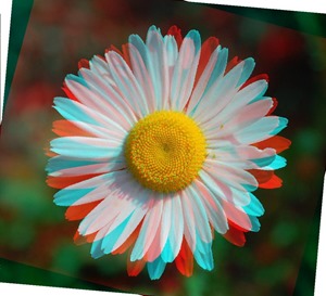
Daisy: Rotate Red 0o, Green 10o, Blue 20o

Daisy Rotate Red 0 Green 10 Blue 20 

Sample Source Code

This article is accompanied by a sample source code Visual Studio project which is available for download .

Using the Sample Application

A Sample Application has been included in the sample source code that accompanies this article. The sample application serves as an implementation of the concepts discussed throughout this article. Concepts can be easily tested and replicated using the sample application.

Daisy: Rotate Red 15o, Green 5o, Blue 10o

Daisy Rotate Red 15 Green 5 Blue 10

When using the sample application users are able to load source/input from the local system by clicking the Load Image button. Required user input via the user interface can be found in the form of three numeric up/down controls labelled Blue, Green and Red respectively. Each control represents the degree to which the related colour component should be rotated. Possible input values range from –360 to 360. Positive values result in clockwise rotation, whereas negative values result in counter clockwise rotation. The sample application enables users to save result to the local file system by clicking the Save Image button.

The following image is a screenshot of the Image Transform Rotate sample application in action:

Image Transform Rotate Sample Application

Image Rotation Transformation

A applied to an from a theoretical point of view is based in . From we learn the following :

In mathematics, transformation geometry (or transformational geometry) is the name of a mathematical and approach to the study of by focusing on groups of , and the properties of figures that are under them. It is opposed to the classical synthetic geometry approach of Euclidean geometry, that focus on geometric constructions.

Rose: Rotate Red –20o, Green 0o, Blue 20o

Rose Rotate Red -20 Green 0 Blue 20

In this article rotation is implemented through applying a set algorithm to the coordinates of each pixel forming part of a source/input . In the corresponding result the calculated rotated pixel coordinates in terms of colour channel values will be assigned to the colour channel values of the original pixel.

The algorithms implemented when calculating  a pixel’s rotated coordinates can be expressed as follows:

RotateX_Algorithm

RotateY_Algorithm

Symbols/variables contained in the algorithms:

  • R (x) : The result of rotating a pixel’s x-coordinate.
  • R (y) : The result of rotating a pixel’s y-coordinate.
  • x : The source pixel’s x-coordinate.
  • y : The source pixel’s y-coordinate.
  • W : The width in pixels of the source .
  • H : The height in pixels of the source .
  • ɑ : The lower case Greek alphabet letter alpha. The value represented by alpha reflects the degree of rotation.

Butterfly: Rotate Red 10o, Green 0o, Blue 0o

Butterfly Rotate Red 10 Green 0 Blue 0

In order to apply a each pixel forming part of the source/input should be iterated. The algorithms expressed above should be applied to each pixel.

The pixel coordinates located at exactly the middle of an can be calculated through dividing the width with a factor of two in regards to the X-coordinate. The Y-coordinate can be calculated through dividing the height also with a factor of two. The algorithms calculate the coordinates of the middle pixel and implements the coordinates as offsets. Implementing the pixel offsets  results in being rotated around the ’s middle, as opposed to the the top left pixel (0,0).

This article and the associated sample source code extends the concept of traditional rotation through implementing rotation on a per colour channel basis. Through user input the individual degree of rotation can be specified for each colour channel, namely Red, Green and Blue. Functionality has been implemented allowing each colour channel to be rotated to a different degree. In essence the algorithms described above have to be implemented three times per pixel iterated.

Daisy: Rotate Red 30o, Green 0o, Blue 180o

Daisy Rotate Red 30 Green 0 Blue 180 

Implementing a Rotation Transformation

The sample source code implements a through the of two : RotateXY and RotateImage.

The RotateXY targets the structure. This method serves as an encapsulation of the logic behind calculating rotating coordinates at a specified angle. The practical C# code implementation of the algorithms discussed in the previous section can be found within this method. The definition as follows:

public static Point RotateXY(this Point source, double degrees,
                                       int offsetX, int offsetY)
{ 
   Point result = new Point();
 
   result.X = (int)(Math.Round((source.X - offsetX) *
              Math.Cos(degrees) - (source.Y - offsetY) *
              Math.Sin(degrees))) + offsetX;

result.Y = (int)(Math.Round((source.X - offsetX) * Math.Sin(degrees) + (source.Y - offsetY) * Math.Cos(degrees))) + offsetY;
return result; }

Rose: Rotate Red –60o, Green 0o, Blue 60o

Rose Rotate Red -60 Green 0 Blue 60

The RotateImage targets the class. This method expects three rotation degree/angle values, each corresponding to a colour channel. Positive degrees result in clockwise rotation and negative values result in counter clockwise rotation.  The definition as follows:

public static Bitmap RotateImage(this Bitmap sourceBitmap,  
                                       double degreesBlue, 
                                      double degreesGreen, 
                                        double degreesRed) 
{ 
    BitmapData sourceData = 
               sourceBitmap.LockBits(new Rectangle(0, 0, 
               sourceBitmap.Width, sourceBitmap.Height), 
               ImageLockMode.ReadOnly, 
               PixelFormat.Format32bppArgb); 

byte[] pixelBuffer = new byte[sourceData.Stride * sourceData.Height];
byte[] resultBuffer = new byte[sourceData.Stride * sourceData.Height];
Marshal.Copy(sourceData.Scan0, pixelBuffer, 0, pixelBuffer.Length);
sourceBitmap.UnlockBits(sourceData);
//Convert to Radians degreesBlue = degreesBlue * Math.PI / 180.0; degreesGreen = degreesGreen * Math.PI / 180.0; degreesRed = degreesRed * Math.PI / 180.0;
//Calculate Offset in order to rotate on image middle int xOffset = (int )(sourceBitmap.Width / 2.0); int yOffset = (int )(sourceBitmap.Height / 2.0);
int sourceXY = 0; int resultXY = 0;
Point sourcePoint = new Point(); Point resultPoint = new Point();
Rectangle imageBounds = new Rectangle(0, 0, sourceBitmap.Width, sourceBitmap.Height);
for (int row = 0; row < sourceBitmap.Height; row++) { for (int col = 0; col < sourceBitmap.Width; col++) { sourceXY = row * sourceData.Stride + col * 4;
sourcePoint.X = col; sourcePoint.Y = row;
if (sourceXY >= 0 && sourceXY + 3 < pixelBuffer.Length) { //Calculate Blue Rotation
resultPoint = sourcePoint.RotateXY(degreesBlue, xOffset, yOffset);
resultXY = (int)(Math.Round( (resultPoint.Y * sourceData.Stride) + (resultPoint.X * 4.0)));
if (imageBounds.Contains(resultPoint) && resultXY >= 0) { if (resultXY + 6 < resultBuffer.Length) { resultBuffer[resultXY + 4] = pixelBuffer[sourceXY];
resultBuffer[resultXY + 7] = 255; }
if (resultXY + 3 < resultBuffer.Length) { resultBuffer[resultXY] = pixelBuffer[sourceXY];
resultBuffer[resultXY + 3] = 255; } }
//Calculate Green Rotation
resultPoint = sourcePoint.RotateXY(degreesGreen, xOffset, yOffset);
resultXY = (int)(Math.Round( (resultPoint.Y * sourceData.Stride) + (resultPoint.X * 4.0)));
if (imageBounds.Contains(resultPoint) && resultXY >= 0) { if (resultXY + 6 < resultBuffer.Length) { resultBuffer[resultXY + 5] = pixelBuffer[sourceXY + 1];
resultBuffer[resultXY + 7] = 255; }
if (resultXY + 3 < resultBuffer.Length) { resultBuffer[resultXY + 1] = pixelBuffer[sourceXY + 1];
resultBuffer[resultXY + 3] = 255; } }
//Calculate Red Rotation
resultPoint = sourcePoint.RotateXY(degreesRed, xOffset, yOffset);
resultXY = (int)(Math.Round( (resultPoint.Y * sourceData.Stride) + (resultPoint.X * 4.0)));
if (imageBounds.Contains(resultPoint) && resultXY >= 0) { if (resultXY + 6 < resultBuffer.Length) { resultBuffer[resultXY + 6] = pixelBuffer[sourceXY + 2]; resultBuffer[resultXY + 7] = 255; }
if (resultXY + 3 < resultBuffer.Length) { resultBuffer[resultXY + 2] = pixelBuffer[sourceXY + 2];
resultBuffer[resultXY + 3] = 255; } } } } }
Bitmap resultBitmap = new Bitmap(sourceBitmap.Width, sourceBitmap.Height);
BitmapData resultData = resultBitmap.LockBits(new Rectangle (0, 0, resultBitmap.Width, resultBitmap.Height), ImageLockMode.WriteOnly, PixelFormat.Format32bppArgb);
Marshal.Copy(resultBuffer, 0, resultData.Scan0, resultBuffer.Length);
resultBitmap.UnlockBits(resultData);
return resultBitmap; }

Daisy: Rotate Red 15o, Green 5o, Blue 5o

Daisy Rotate Red 15 Green 5 Blue 5

Sample Images

This article features a number of sample images. All featured images have been licensed allowing for reproduction.

The sample images featuring an image of a yellow daisy is licensed under the Creative Commons Attribution-Share Alike 2.5 Generic license and can be downloaded from Wikimedia.org.

The sample images featuring an image of a white daisy is licensed under the Creative Commons Attribution-Share Alike 3.0 Unported license and can be downloaded from Wikipedia.

The sample images featuring an image of a CPU is licensed under the Creative Commons Attribution-Share Alike 2.0 Generic license. The original author is credited as Andrew Dunn. The original image can be downloaded from .

The sample images featuring an image of a rose is licensed under the Creative Commons Attribution-Share Alike 3.0 Unported, 2.5 Generic, 2.0 Generic and 1.0 Generic license. The original image can be downloaded from .

The sample images featuring an image of a butterfly is licensed under the Creative Commons Attribution 3.0 Unported license and can be downloaded from Wikimedia.org.

The Original Image

Intel_80486DX2_bottom

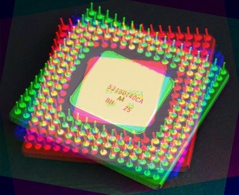
CPU: Rotate Red 90o, Green 0o, Blue –30o

CPU Rotate Red 90 Green 0 Blue -30

CPU: Rotate Red 0o, Green 10o, Blue 0o

CPU Rotate Red 0 Green 10 Blue 0

CPU: Rotate Red –4o, Green 4o, Blue 6o

CPU Rotate Red -4 Green 4 Blue 6

CPU: Rotate Red 10o, Green 0o, Blue 0o

CPU Rotate Red 10 Green 0 Blue 0

CPU: Rotate Red 10o, Green –5o, Blue 0o

CPU Rotate Red 10 Green -5 Blue 0

CPU: Rotate Red 10o, Green 0o, Blue 10o

CPU Rotate Red 10 Green 0 Blue 10

CPU: Rotate Red –10o, Green 10o, Blue 0o

CPU Rotate Red -10 Green 10 Blue 0

CPU: Rotate Red 30o, Green –30o, Blue 0o

CPU Rotate Red 30 Green -30 Blue 0

CPU: Rotate Red 40o, Green 20o, Blue 0o

CPU Rotate Red 40 Green 20 Blue 0

CPU: Rotate Red 40o, Green 20o, Blue 0o

CPU Rotate Red 60 Green 30 Blue 0

Related Articles and Feedback

Feedback and questions are always encouraged. If you know of an alternative implementation or have ideas on a more efficient implementation please share in the comments section.

I’ve published a number of articles related to imaging and images of which you can find URL links here:

C# How to: Image Colour Average

Article purpose

This article’s intension is focussed on providing a discussion on the tasks involved in implementing Image Colour Averaging. Pixel colour averages are calculated from neighbouring pixels.

Sample source code

This article is accompanied by a sample source code Visual Studio project which is available for download .

Using the Sample Application

The sample source code associated with this article includes a based sample application. The sample application is provided with the intention of illustrating the concepts explored in this article. In addition the sample application serves as a means of testing and replicating results.

By clicking the Load Image button users are able to select input/source from the local system. On the right hand side of the screen various controls enable the user to control the implementation of colour averaging. The three labelled Red, Green and Blue relates to whether an individual colour component is to be included in calculating colour averages.

The filter intensity can be specified through selecting a filter size from the dropdown , specifying higher values will result in output images expressing more colour averaging intensity.

Additional image filter effects can be achieved through implementing colour component shifting/swapping. When colour components are shifted left the result will be:

  • Blue is set to the original value of the Red component.
  • Red is set to the original value of the Green component.
  • Green is set to the original value of the Blue component.

When colour components are shifted right the result will be:

  • Red is set to the original value of the Blue component
  • Blue is set to the original value of the Green component
  • Green is set to the original value of the Red Component

Resulting can be saved by the user to the local file system by clicking the Save Image button. The following image is a screenshot of the Image Colour Average sample application in action:

Image Colour Average Sample Application

Averaging Colours

In this article and the accompanying sample source code colour averaging is implemented on a per pixel basis. An average colour value is calculated based on a pixel’s neighbouring pixels’ colour. Determining neighbouring pixels in the sample source code has been implemented in much the same method as . The major difference to is the absence of a fixed /.

Additional resulting visual effects can be achieved through various options/settings implemented whilst calculating colour averages. Additional options include being able to specify which colour component averages to implement. Furthermore colour components can be swapped/shifted around.

The sample source code implements the AverageColoursFilter , targeting the class. The extent or degree to which colour averaging will be evident in resulting can be controlled through specifying different values set to the matrixSize parameter. The matrixSize parameter in essence determines the number of neighbouring pixels involved in calculating an average colour.

The individual pixel colour components Red, Green and Blue can either be included or excluded in calculating averages. The three method boolean parameters applyBlue, applyGreen and applyRed will determine an individual colour components inclusion in averaging calculations. If a colour component is to be excluded from averaging the resulting will instead express the original source/input image’s colour component.

The intensity of a specific colour component average can be applied to another colour component by means of swapping/shifting colour components, which is indicated through the shiftType method parameter.

The following code snippet provides the implementation of the AverageColoursFilter :

public static Bitmap AverageColoursFilter(
                            this Bitmap sourceBitmap,  
                            int matrixSize,   
                            bool applyBlue = true, 
                            bool applyGreen = true, 
                            bool applyRed = true, 
                            ColorShiftType shiftType = 
                            ColorShiftType.None)  
{ 
    BitmapData sourceData =  
               sourceBitmap.LockBits(new Rectangle(0, 0, 
               sourceBitmap.Width, sourceBitmap.Height), 
               ImageLockMode.ReadOnly,  
               PixelFormat.Format32bppArgb); 

byte[] pixelBuffer = new byte[sourceData.Stride * sourceData.Height];
byte[] resultBuffer = new byte[sourceData.Stride * sourceData.Height];
Marshal.Copy(sourceData.Scan0, pixelBuffer, 0, pixelBuffer.Length);
sourceBitmap.UnlockBits(sourceData);
int filterOffset = (matrixSize - 1) / 2; int calcOffset = 0;
int byteOffset = 0;
int blue = 0; int green = 0; int red = 0;
for (int offsetY = filterOffset; offsetY < sourceBitmap.Height - filterOffset; offsetY++) { for (int offsetX = filterOffset; offsetX < sourceBitmap.Width - filterOffset; offsetX++) { byteOffset = offsetY * sourceData.Stride + offsetX * 4;
blue = 0; green = 0; red = 0;
for (int filterY = -filterOffset; filterY <= filterOffset; filterY++) { for (int filterX = -filterOffset; filterX <= filterOffset; filterX++) { calcOffset = byteOffset + (filterX * 4) + (filterY * sourceData.Stride);
blue += pixelBuffer[calcOffset]; green += pixelBuffer[calcOffset + 1]; red += pixelBuffer[calcOffset + 2]; } }
blue = blue / matrixSize; green = green / matrixSize; red = red / matrixSize;
if (applyBlue == false) { blue = pixelBuffer[byteOffset]; }
if (applyGreen == false) { green = pixelBuffer[byteOffset + 1]; }
if (applyRed == false) { red = pixelBuffer[byteOffset + 2]; }
if (shiftType == ColorShiftType.None) { resultBuffer[byteOffset] = (byte)blue; resultBuffer[byteOffset + 1] = (byte)green; resultBuffer[byteOffset + 2] = (byte)red; resultBuffer[byteOffset + 3] = 255; } else if (shiftType == ColorShiftType.ShiftLeft) { resultBuffer[byteOffset] = (byte)green; resultBuffer[byteOffset + 1] = (byte)red; resultBuffer[byteOffset + 2] = (byte)blue; resultBuffer[byteOffset + 3] = 255; } else if (shiftType == ColorShiftType.ShiftRight) { resultBuffer[byteOffset] = (byte)red; resultBuffer[byteOffset + 1] = (byte)blue; resultBuffer[byteOffset + 2] = (byte)green; resultBuffer[byteOffset + 3] = 255; } } }
Bitmap resultBitmap = new Bitmap(sourceBitmap.Width, sourceBitmap.Height);
BitmapData resultData = resultBitmap.LockBits(new Rectangle(0, 0, resultBitmap.Width, resultBitmap.Height), ImageLockMode.WriteOnly, PixelFormat.Format32bppArgb);
Marshal.Copy(resultBuffer, 0, resultData.Scan0, resultBuffer.Length);
resultBitmap.UnlockBits(resultData);
return resultBitmap; }

The definition of the ColorShiftType :

public enum ColorShiftType  
{
    None, 
    ShiftLeft, 
    ShiftRight 
}

Sample

The original image used in generating the sample images that form part of this article, has been licensed under the Attribution-Share Alike , , and license. The can be from .

Original Image

Rose_Amber_Flush_20070601

Colour Average Blue Size 11

Colour Average Blue Size 11

Colour Average Blue Size 11 Shift Left

Colour Average Blue Size 11 Shift Left

Colour Average Blue Size 11 Shift Right

Colour Average Blue Size 11 Shift Right

Colour Average Green Size 11 Shift Right

Colour Average Green Size 11 Shift Right

Colour Average Green, Blue Size 11

Colour Average Green, Blue Size 11

Colour Average Green, Blue Size 11 Shift Left

Colour Average Green, Blue Size 11 Shift Left

Colour Average Green, Blue Size 11 Shift Right

Colour Average Green, Blue Size 11 Shift Right

Colour Average Red Size 11

Colour Average Red Size 11

Colour Average Red Size 11 Shift Left

Colour Average Red Size 11 Shift Left

Colour Average Red, Blue Size 11

Colour Average Red, Blue Size 11

Colour Average Red, Blue Size 11 Shift Left

Colour Average Red, Blue Size 11 Shift Left

Colour Average Red, Green Size 11

Colour Average Red, Green Size 11

Colour Average Red, Green Size 11 Shift Left

Colour Average Red, Green Size 11 Shift Left

Colour Average Red, Green Size 11 Shift Right

Colour Average Red, Green Size 11 Shift Right

Colour Average Red, Green, Blue Size 11

Colour Average Red, Green, Blue Size 11

Colour Average Red, Green, Blue Size 11 Shift Left

Colour Average Red, Green, Blue Size 11 Shift Left

Colour Average Red, Green, Blue Size 11 Shift Right

Colour Average Red, Green, Blue Size 11 Shift Right

Related Articles and Feedback

Feedback and questions are always encouraged. If you know of an alternative implementation or have ideas on a more efficient implementation please share in the comments section.

I’ve published a number of articles related to imaging and images of which you can find URL links here:

C# How to: Image Unsharp Mask

Article purpose

The purpose of this article is to explore and illustrate the concept of . This article implements in the form of a 3×3 , 5×5 , 3×3 Mean filter and a 5×5 Mean filter.

Sample Source code

This article is accompanied by a sample source code Visual Studio project which is available for download .

Using the Sample Application

The sample source code associated with this article includes a based sample application implementing the concepts explored throughout this article.

When using the Image Unsharp Mask sample application users can select a source/input image from the local system by clicking the Load Image button. The dropdown at the bottom of the screen allows the user to select an unsharp masking variation. On the right hand side of the screen users can specify the level/intensity of resulting .

Clicking the Save Image button allows a user to save resulting to the local file system. The image below is a screenshot of the Image Unsharp Mask sample application in action:

Image Unsharp Mask Sample Application

What is Image Unsharp Masking?

A good definition of can be found on :

Unsharp masking (USM) is an image manipulation technique, often available in software.

The "unsharp" of the name derives from the fact that the technique uses a blurred, or "unsharp", positive image to create a "mask" of the original image. The unsharped mask is then combined with the negative image, creating an image that is less blurry than the original. The resulting image, although clearer, probably loses accuracy with respect to the image’s subject. In the context of , an unsharp mask is generally a or filter that amplifies high-frequency components.

In this article we implement by first creating a blurred copy of a source/input then subtracting the blurred from the original , which is known as the mask. Increased is achieved by adding a factor of the mask to the original .

Applying a Convolution Matrix filter

The sample source code provides the definition for the ConvolutionFilter targeting the class. method is invoked when implementing . The definition of the ConvolutionFilter as follows:

 private static Bitmap ConvolutionFilter(Bitmap sourceBitmap,  
                                     double[,] filterMatrix,  
                                          double factor = 1,  
                                               int bias = 0,  
                                     bool grayscale = false )  
{ 
     BitmapData sourceData = sourceBitmap.LockBits(new Rectangle (0, 0, 
                              sourceBitmap.Width, sourceBitmap.Height), 
                                                ImageLockMode.ReadOnly,  
                                          PixelFormat.Format32bppArgb); 

byte[] pixelBuffer = new byte[sourceData.Stride * sourceData.Height]; byte[] resultBuffer = new byte[sourceData.Stride * sourceData.Height];
Marshal.Copy(sourceData.Scan0, pixelBuffer, 0, pixelBuffer.Length); sourceBitmap.UnlockBits(sourceData);
if (grayscale == true) { float rgb = 0;
for (int k = 0; k < pixelBuffer.Length; k += 4) { rgb = pixelBuffer[k] * 0.11f; rgb += pixelBuffer[k + 1] * 0.59f; rgb += pixelBuffer[k + 2] * 0.3f;
pixelBuffer[k] = (byte )rgb; pixelBuffer[k + 1] = pixelBuffer[k]; pixelBuffer[k + 2] = pixelBuffer[k]; pixelBuffer[k + 3] = 255; } }
double blue = 0.0; double green = 0.0; double red = 0.0;
int filterWidth = filterMatrix.GetLength(1); int filterHeight = filterMatrix.GetLength(0);
int filterOffset = (filterWidth-1) / 2; int calcOffset = 0;
int byteOffset = 0;
for (int offsetY = filterOffset; offsetY < sourceBitmap.Height - filterOffset; offsetY++) { for (int offsetX = filterOffset; offsetX < sourceBitmap.Width - filterOffset; offsetX++) { blue = 0; green = 0; red = 0;
byteOffset = offsetY * sourceData.Stride + offsetX * 4;
for (int filterY = -filterOffset; filterY <= filterOffset; filterY++) { for (int filterX = -filterOffset; filterX <= filterOffset; filterX++) {
calcOffset = byteOffset + (filterX * 4) + (filterY * sourceData.Stride);
blue += (double)(pixelBuffer[calcOffset]) * filterMatrix[filterY + filterOffset, filterX + filterOffset];
green += (double)(pixelBuffer[calcOffset + 1]) * filterMatrix[filterY + filterOffset, filterX + filterOffset];
red += (double)(pixelBuffer[calcOffset + 2]) * filterMatrix[filterY + filterOffset, filterX + filterOffset]; } }
blue = factor * blue + bias; green = factor * green + bias; red = factor * red + bias;
if (blue > 255) { blue = 255; } else if (blue < 0) { blue = 0; }
if (green > 255) { green = 255; } else if (green < 0) { green = 0; }
if (red > 255) { red = 255; } else if (red < 0) { red = 0; }
resultBuffer[byteOffset] = (byte )(blue); resultBuffer[byteOffset + 1] = (byte )(green); resultBuffer[byteOffset + 2] = (byte )(red); resultBuffer[byteOffset + 3] = 255; } }
Bitmap resultBitmap = new Bitmap(sourceBitmap.Width, sourceBitmap.Height); BitmapData resultData = resultBitmap.LockBits(new Rectangle (0, 0, resultBitmap.Width, resultBitmap.Height), ImageLockMode.WriteOnly, PixelFormat.Format32bppArgb);
Marshal.Copy(resultBuffer, 0, resultData.Scan0, resultBuffer.Length); resultBitmap.UnlockBits(resultData);
return resultBitmap; }

Subtracting and Adding Images

An important step required when implementing comes in the form of creating a mask by subtracting a blurred copy from the original and then adding a factor of the mask to the original . In order to achieve increased performance the sample source code combines the process of creating the mask and adding the mask to the original .

The SubtractAddFactorImage iterates every pixel that forms part of an . In a single step the blurred pixel is subtracted from the original pixel, multiplied by a user specified factor and then added to the original pixel. The definition of the SubtractAddFactorImage as follows:

private static Bitmap SubtractAddFactorImage( 
                              this Bitmap subtractFrom, 
                                  Bitmap subtractValue, 
                                   float factor = 1.0f) 
{ 
    BitmapData sourceData =  
               subtractFrom.LockBits(new Rectangle (0, 0, 
               subtractFrom.Width, subtractFrom.Height), 
               ImageLockMode.ReadOnly, 
               PixelFormat.Format32bppArgb); 

byte[] sourceBuffer = new byte[sourceData.Stride * sourceData.Height];
Marshal.Copy(sourceData.Scan0, sourceBuffer, 0, sourceBuffer.Length);
byte[] resultBuffer = new byte[sourceData.Stride * sourceData.Height];
BitmapData subtractData = subtractValue.LockBits(new Rectangle (0, 0, subtractValue.Width, subtractValue.Height), ImageLockMode.ReadOnly, PixelFormat.Format32bppArgb);
byte[] subtractBuffer = new byte[subtractData.Stride * subtractData.Height];
Marshal.Copy(subtractData.Scan0, subtractBuffer, 0, subtractBuffer.Length);
subtractFrom.UnlockBits(sourceData); subtractValue.UnlockBits(subtractData);
double blue = 0; double green = 0; double red = 0;
for (int k = 0; k < resultBuffer.Length && k < subtractBuffer.Length; k += 4) { blue = sourceBuffer[k] + (sourceBuffer[k] - subtractBuffer[k]) * factor;
green = sourceBuffer[k + 1] + (sourceBuffer[k + 1] - subtractBuffer[k + 1]) * factor;
red = sourceBuffer[k + 2] + (sourceBuffer[k + 2] - subtractBuffer[k + 2]) * factor;
blue = (blue < 0 ? 0 : (blue > 255 ? 255 : blue)); green = (green < 0 ? 0 : (green > 255 ? 255 : green)); red = (red < 0 ? 0 : (red > 255 ? 255 : red));
resultBuffer[k] = (byte )blue; resultBuffer[k + 1] = (byte )green; resultBuffer[k + 2] = (byte )red; resultBuffer[k + 3] = 255; }
Bitmap resultBitmap = new Bitmap (subtractFrom.Width, subtractFrom.Height);
BitmapData resultData = resultBitmap.LockBits(new Rectangle (0, 0, resultBitmap.Width, resultBitmap.Height), ImageLockMode.WriteOnly, PixelFormat.Format32bppArgb);
Marshal.Copy(resultBuffer, 0, resultData.Scan0, resultBuffer.Length);
resultBitmap.UnlockBits(resultData);
return resultBitmap; }

Matrix Definition

The image blurring filters implemented by the sample source code relies on static / values defined in the Matrix class. The variants of implemented are: 3×3 , 5×5 Gaussian, 3×3 Mean and 5×5 Mean. The definition of the Matrix class is detailed by the following code snippet:

public static class Matrix
{
    public static double[,] Gaussian3x3
    {
        get
        {
            return new double[,]
            { { 1, 2, 1, }, 
              { 2, 4, 2, }, 
              { 1, 2, 1, }, };
        }
    }

public static double[,] Gaussian5x5Type1 { get { return new double[,] { { 2, 04, 05, 04, 2 }, { 4, 09, 12, 09, 4 }, { 5, 12, 15, 12, 5 }, { 4, 09, 12, 09, 4 }, { 2, 04, 05, 04, 2 }, }; } }
public static double[,] Mean3x3 { get { return new double[,] { { 1, 1, 1, }, { 1, 1, 1, }, { 1, 1, 1, }, }; } }
public static double[,] Mean5x5 { get { return new double[,] { { 1, 1, 1, 1, 1 }, { 1, 1, 1, 1, 1 }, { 1, 1, 1, 1, 1 }, { 1, 1, 1, 1, 1 }, { 1, 1, 1, 1, 1 }, }; } } }

Implementing Image Unsharpening

This article explores four variants of , relating to the four types of image blurring discussed in the previous section. The sample source code defines the following : UnsharpGaussian3x3, UnsharpGaussian5x5, UnsharpMean3x3 and UnsharpMean5x5. All four methods are defined as targeting the class. When looking at the sample images in the following section you will notice the correlation between increased and enhanced . The definition as follows:

public static Bitmap UnsharpGaussian3x3( 
                                 this Bitmap sourceBitmap,  
                                 float factor = 1.0f) 
{
    Bitmap blurBitmap = ExtBitmap.ConvolutionFilter( 
                                  sourceBitmap,  
                                  Matrix.Gaussian3x3,  
                                  1.0 / 16.0); 

Bitmap resultBitmap = sourceBitmap.SubtractAddFactorImage( blurBitmap, factor);
return resultBitmap; }
public static Bitmap UnsharpGaussian5x5( this Bitmap sourceBitmap, float factor = 1.0f) { Bitmap blurBitmap = ExtBitmap.ConvolutionFilter( sourceBitmap, Matrix.Gaussian5x5Type1, 1.0 / 159.0);
Bitmap resultBitmap = sourceBitmap.SubtractAddFactorImage( blurBitmap, factor);
return resultBitmap; } public static Bitmap UnsharpMean3x3( this Bitmap sourceBitmap, float factor = 1.0f) { Bitmap blurBitmap = ExtBitmap.ConvolutionFilter( sourceBitmap, Matrix.Mean3x3, 1.0 / 9.0);
Bitmap resultBitmap = sourceBitmap.SubtractAddFactorImage( blurBitmap, factor);
return resultBitmap; }
public static Bitmap UnsharpMean5x5( this Bitmap sourceBitmap, float factor = 1.0f) { Bitmap blurBitmap = ExtBitmap.ConvolutionFilter( sourceBitmap, Matrix.Mean5x5, 1.0 / 25.0);
Bitmap resultBitmap = sourceBitmap.SubtractAddFactorImage( blurBitmap, factor);
return resultBitmap; }

Sample Images

The used in rendering the sample images shown in this article is licensed under the Creative Commons Attribution-Share Alike 3.0 Unported license and can be from :

The Original Image

W-A-S-D

Unsharp Gaussian 3×3

Unsharp Gaussian 3x3

Unsharp Gaussian 5×5

Unsharp Gaussian 5x5

Unsharp Mean 3×3

Unsharp Mean 3x3

Unsharp Gaussian 5×5

Unsharp Mean 5x5

Related Articles and Feedback

Feedback and questions are always encouraged. If you know of an alternative implementation or have ideas on a more efficient implementation please share in the comments section.

I’ve published a number of articles related to imaging and images of which you can find URL links here:


Dewald Esterhuizen

Blog Stats

  • 869,871 hits

Enter your email address to follow and receive notifications of new posts by email.

Join 228 other subscribers

Archives

RSS SoftwareByDefault on MSDN

  • An error has occurred; the feed is probably down. Try again later.