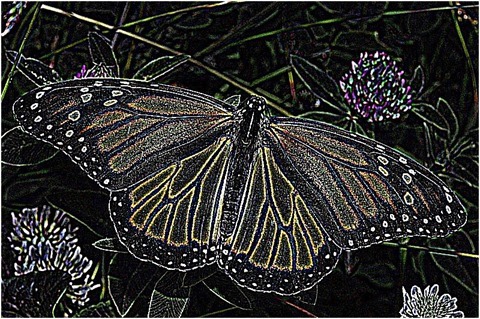
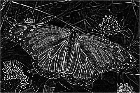
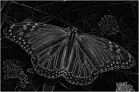
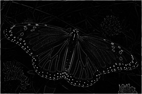
Posts Tagged 'Edge enhance'

C# How to: Fuzzy Blur Filter

Article Purpose

This article serves to illustrate the concepts involved in implementing a Fuzzy Blur Filter. This filter results in rendering  non-photo realistic images which express a certain artistic effect.

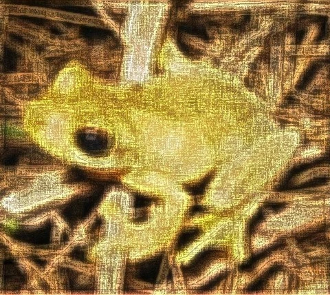
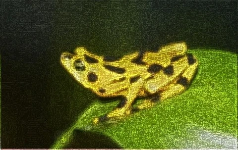
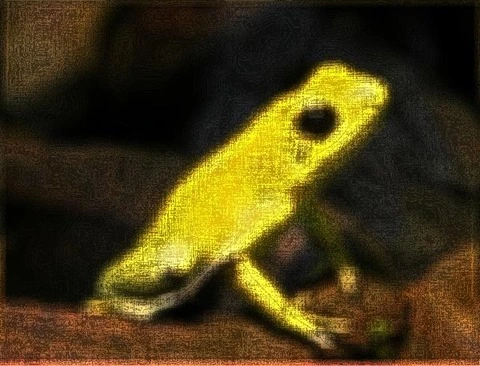
Frog: Filter Size 19×19

Frog: Filter Size 19x19

Sample Source Code

This article is accompanied by a sample source code Visual Studio project which is available for download here.

Using the Sample Application

The sample source code accompanying this article includes a based test application. The concepts explored throughout this article can be replicated/tested using the sample application.

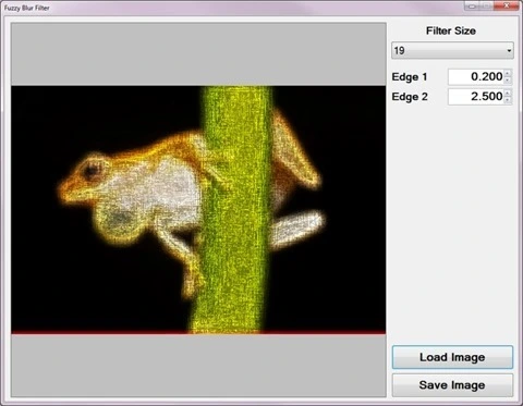
When executing the sample application the user interface exposes a number of configurable options:

  • Loading and Saving Images – Users are able to load source/input from the local system by clicking the Load Image button. Clicking the Save Image button allow users to save filter result .
  • Filter Size – The specified filter size affects the filter intensity. Smaller filter sizes result in less blurry being rendered, whereas larger filter sizes result in more blurry being rendered.
  • Edge Factors – The contrast of fuzzy expressed in resulting depend on the specified edge factor values. Values less than one result in detected being darkened and values greater than one result in detected image edges being lightened.

The following image is a screenshot of the Fuzzy Blur Filter sample application in action:

Fuzzy Blur Filter Sample Application

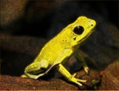
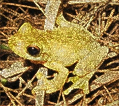
Frog: Filter Size 9×9

Frog: Filter Size 9x9

Fuzzy Blur Overview

The Fuzzy Blur Filter relies on the interference of when performing in order to create a fuzzy effect. In addition results from performing a .

The steps involved in performing a Fuzzy Blur Filter can be described as follows:

  1. Edge Detection and Enhancement – Using the first edge factor specified enhance by performing Boolean Edge detection. Being sensitive to , a fair amount of detected will actually be in addition to actual .
  2. Mean Filter Blur – Using the edge enhanced created in the previous step perform a blur. The enhanced edges will be blurred since a does not have edge preservation properties. The size of the implemented depends on a user specified value.
  3. Edge Detection and Enhancement –  Using the blurred created in the previous step once again perform Boolean Edge detection, enhancing detected edges according to the second edge factor specified.

Frog: Filter Size 9×9

Frog: Filter Size 9x9

Mean Filter

A Blur, also known as a , can be performed through . The size of the / implemented when preforming will be determined through user input.

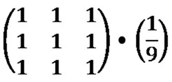
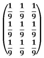
Every / element should be set to one. The resulting value should be multiplied by a factor value equating to one divided by the / size. As an example, a / size of 3×3 can be expressed as follows:

Mean Kernel

An alternative expression can also be:

Mean Kernel

Frog: Filter Size 9×9

Frog: Filter Size 9x9

Boolean Edge Detection without a local threshold

When performing Boolean Edge Detection a local threshold should be implemented in order to exclude . In this article we rely on the interference of in order to render a fuzzy effect. By not implementing a local threshold when performing Boolean Edge detection the sample source code ensures sufficient interference from .

The steps involved in performing Boolean Edge Detection without a local threshold can be described as follows:

  1. Calculate Neighbourhood Mean – Iterate each forming part of the source/input . Using a 3×3 size calculate the mean value of the neighbourhood surrounding the currently being iterated.
  2. Create Mean comparison Matrix – Once again using a 3×3 size compare each neighbourhood to the newly calculated mean value. Create a temporary 3×3 size , each element’s value should be the result of mean comparison. Should the value expressed by a neighbourhood exceed the mean value the corresponding temporary element should be set to one. When the calculated mean value exceeds the value of a neighbourhood the corresponding temporary  element should be set to zero.
  3. Compare Edge Masks – Using sixteen predefined edge masks compare the temporary created in the previous step to each edge mask. If the temporary matches one of the predefined edge masks multiply the specified factor to the currently being iterated.

Note: A detailed article on Boolean Edge detection implementing a local threshold can be found here:

Frog: Filter Size 9×9

Frog: Filter Size 9x9

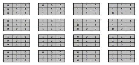
The sixteen predefined edge masks each represent an in a different direction. The predefined edge masks can be expressed as:

Boolean Edge Masks

Frog: Filter Size 13×13

Frog: Filter Size 13x13

Implementing a Mean Filter

The sample source code defines the MeanFilter method, an targeting the class. The definition listed as follows:

private static Bitmap MeanFilter(this Bitmap sourceBitmap, 
                                 int meanSize)
{
    byte[] pixelBuffer = sourceBitmap.GetByteArray(); 
    byte[] resultBuffer = new byte[pixelBuffer.Length];

double blue = 0.0, green = 0.0, red = 0.0; double factor = 1.0 / (meanSize * meanSize);
int imageStride = sourceBitmap.Width * 4; int filterOffset = meanSize / 2; int calcOffset = 0, filterY = 0, filterX = 0;
for (int k = 0; k + 4 < pixelBuffer.Length; k += 4) { blue = 0; green = 0; red = 0; filterY = -filterOffset; filterX = -filterOffset;
while (filterY <= filterOffset) { calcOffset = k + (filterX * 4) + (filterY * imageStride);
calcOffset = (calcOffset < 0 ? 0 : (calcOffset >= pixelBuffer.Length - 2 ? pixelBuffer.Length - 3 : calcOffset));
blue += pixelBuffer[calcOffset]; green += pixelBuffer[calcOffset + 1]; red += pixelBuffer[calcOffset + 2];
filterX++;
if (filterX > filterOffset) { filterX = -filterOffset; filterY++; } }
resultBuffer[k] = ClipByte(factor * blue); resultBuffer[k + 1] = ClipByte(factor * green); resultBuffer[k + 2] = ClipByte(factor * red); resultBuffer[k + 3] = 255; }
return resultBuffer.GetImage(sourceBitmap.Width, sourceBitmap.Height); }

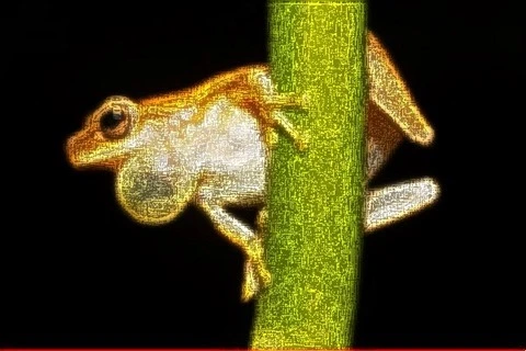
Frog: Filter Size 19×19

Frog: Filter Size 19x19

Implementing Boolean Edge Detection

Boolean Edge detection is performed in the sample source code through the implementation of the BooleanEdgeDetectionFilter method. This method has been defined as an targeting the class.

The following code snippet provides the definition of the BooleanEdgeDetectionFilter :

public static Bitmap BooleanEdgeDetectionFilter( 
       this Bitmap sourceBitmap, float edgeFactor) 
{
    byte[] pixelBuffer = sourceBitmap.GetByteArray(); 
    byte[] resultBuffer = new byte[pixelBuffer.Length]; 
    Buffer.BlockCopy(pixelBuffer, 0, resultBuffer, 
                     0, pixelBuffer.Length); 

List<string> edgeMasks = GetBooleanEdgeMasks(); int imageStride = sourceBitmap.Width * 4; int matrixMean = 0, pixelTotal = 0; int filterY = 0, filterX = 0, calcOffset = 0; string matrixPatern = String.Empty;
for (int k = 0; k + 4 < pixelBuffer.Length; k += 4) { matrixPatern = String.Empty; matrixMean = 0; pixelTotal = 0; filterY = -1; filterX = -1;
while (filterY < 2) { calcOffset = k + (filterX * 4) + (filterY * imageStride);
calcOffset = (calcOffset < 0 ? 0 : (calcOffset >= pixelBuffer.Length - 2 ? pixelBuffer.Length - 3 : calcOffset)); matrixMean += pixelBuffer[calcOffset]; matrixMean += pixelBuffer[calcOffset + 1]; matrixMean += pixelBuffer[calcOffset + 2];
filterX += 1;
if (filterX > 1) { filterX = -1; filterY += 1; } }
matrixMean = matrixMean / 9; filterY = -1; filterX = -1;
while (filterY < 2) { calcOffset = k + (filterX * 4) + (filterY * imageStride);
calcOffset = (calcOffset < 0 ? 0 : (calcOffset >= pixelBuffer.Length - 2 ? pixelBuffer.Length - 3 : calcOffset));
pixelTotal = pixelBuffer[calcOffset]; pixelTotal += pixelBuffer[calcOffset + 1]; pixelTotal += pixelBuffer[calcOffset + 2]; matrixPatern += (pixelTotal > matrixMean ? "1" : "0"); filterX += 1;
if (filterX > 1) { filterX = -1; filterY += 1; } }
if (edgeMasks.Contains(matrixPatern)) { resultBuffer[k] = ClipByte(resultBuffer[k] * edgeFactor);
resultBuffer[k + 1] = ClipByte(resultBuffer[k + 1] * edgeFactor);
resultBuffer[k + 2] = ClipByte(resultBuffer[k + 2] * edgeFactor); } }
return resultBuffer.GetImage(sourceBitmap.Width, sourceBitmap.Height); }

Frog: Filter Size 13×13

Frog: Filter Size 13x13

The predefined edge masks implemented in mean comparison have been wrapped by the GetBooleanEdgeMasks method. The definition as follows:

public static List<string> GetBooleanEdgeMasks() 
{
    List<string> edgeMasks = new List<string>(); 

edgeMasks.Add("011011011"); edgeMasks.Add("000111111"); edgeMasks.Add("110110110"); edgeMasks.Add("111111000"); edgeMasks.Add("011011001"); edgeMasks.Add("100110110"); edgeMasks.Add("111011000"); edgeMasks.Add("111110000"); edgeMasks.Add("111011001"); edgeMasks.Add("100110111"); edgeMasks.Add("001011111"); edgeMasks.Add("111110100"); edgeMasks.Add("000011111"); edgeMasks.Add("000110111"); edgeMasks.Add("001011011"); edgeMasks.Add("110110100");
return edgeMasks; }

Frog: Filter Size 19×19

Frog: Filter Size 19x19

Implementing a Fuzzy Blur Filter

The FuzzyEdgeBlurFilter method serves as the implementation of a Fuzzy Blur Filter. As discussed earlier a Fuzzy Blur Filter involves enhancing through Boolean Edge detection, performing a blur and then once again performing Boolean Edge detection. This method has been defined as an extension method targeting the class.

The following code snippet provides the definition of the FuzzyEdgeBlurFilter method:

public static Bitmap FuzzyEdgeBlurFilter(this Bitmap sourceBitmap,  
                                         int filterSize,  
                                         float edgeFactor1,  
                                         float edgeFactor2) 
{
    return  
    sourceBitmap.BooleanEdgeDetectionFilter(edgeFactor1). 
    MeanFilter(filterSize).BooleanEdgeDetectionFilter(edgeFactor2); 
}

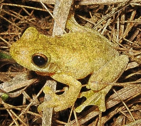
Frog: Filter Size 3×3

Frog: Filter Size 3x3

Sample Images

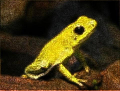
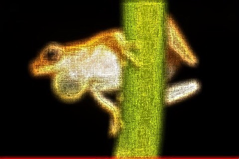
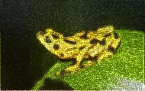
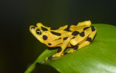
This article features a number of sample images. All featured images have been licensed allowing for reproduction. The following images feature as sample images:

Litoria_tyleri

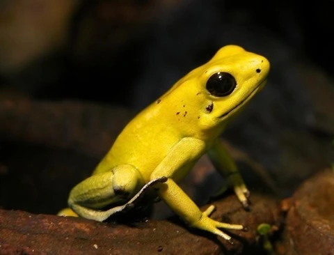
Schrecklicherpfeilgiftfrosch-01

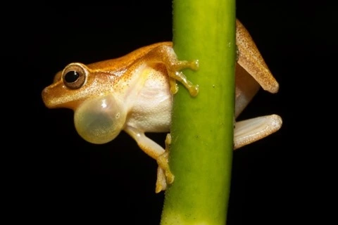
Dendropsophus_microcephalus_-_calling_male_(Cope,_1886)

Atelopus_zeteki1

Related Articles and Feedback

Feedback and questions are always encouraged. If you know of an alternative implementation or have ideas on a more efficient implementation please share in the comments section.

I’ve published a number of articles related to imaging and images of which you can find URL links here:

C# How to: Image Boundary Extraction

Article Purpose

This article explores various concepts, which feature in combination when implementing Image Boundary Extraction. Concepts covered within this article include: Morphological and , Addition and Subtraction, Boundary Sharpening, Boundary Tracing and Boundary Extraction.

Parrot: Boundary Extraction, 3×3, Red, Green, Blue

Parrot: Boundary Extraction, 3x3, Red, Greed, Blue

Sample Source Code

This article is accompanied by a sample source code Visual Studio project which is available for download .

Using the Sample Application

This article’s accompanying sample source code includes the definition of a sample application. The sample application serves as an implementation of the concepts discussed in this article. In using the sample application concepts can be easily tested and replicated.

The sample application has been defined as a . The user interface enables the user to configure several options which influence the output produced from filtering processes. The following section describes the options available to a user when executing the sample application:

  • Loading and Saving files – Users can specify source/input through clicking the Load Image button. If desired, resulting filtered can be saved to the local system when clicking the Save Image button.
  • Filter Type – The types of filters implemented represent variations on Image Boundary Extraction. The supported filter types are: Conventional Boundary extraction, Boundary Sharpening and Boundary Tracing.
  • Filter Size – Filter intensity/strength will mostly be reliant on the filter size implemented. A Filter size represents the number of neighbouring examined when applying filters.
  • Colours Applied – The sample source code and sample application provides functionality allowing a filter to only effect user specified colour components. Colour components are represented in the form of an RGB colour scheme. The inclusion or exclusion of the colour components Red, Green and Blue will be determined through user configuration.
  • Structuring Element – As mentioned, the Filter Size option determines the size of neighbourhood examined. The ’s setup determine the neighbouring   within the neighbourhood size bounds that should be used as input when calculating filter results.

The following is a screenshot of the Image Boundary Extraction sample application in action:

Image Boundary Extaction Sample  Application

Parrot: Boundary Extraction, 3×3, Green

Parrot: Boundary Extraction, 3x3, Green

Morphological Boundary Extraction

Image Boundary Extraction can be considered a method of . In contrast to more commonly implemented   methods, Image Boundary Extraction originates from Morphological Image Filters.

When drawing a comparison, Image Boundary Extraction and express strong similarities. results from the difference in and . Considered from a different point of view, creating one expressing thicker edges and another expressing thinner edges provides the means to calculate the difference in edges.

Image Boundary Extraction implements the same concept as . The base concept can be regarded as calculating the difference between two which rendered the same , but expressing a difference in . Image Boundary Extraction relies on calculating the difference between either and the source or and the source . The difference between and in most cases result in more of difference than the difference between and the source or and the source . The result of Image Boundary Extraction representing less of a difference than can be observed in Image Boundary Extraction being expressed in finer/smaller width lines.

is another method of which functions along the same basis. Edges are determined by calculating the difference between two , each having been filtered from the same source , using a of differing intensity levels.

Parrot: Boundary Extraction, 3×3, Red, Green, Blue

Parrot: Boundary Extraction, 3x3, Red, Green, Blue

Boundary Sharpening

The concept of Boundary Sharpening refers to enhancing or sharpening the boundaries or edges expressed in a source/input . Boundaries can be easily determined or extracted as discussed earlier when exploring Boundary Extraction.

The steps involved in performing Boundary Sharpening can be described as follows:

  1. Extract Boundaries – Determine boundaries by performing and calculating the difference between the dilated and the source .
  2. Match Source Edges and Extracted Boundaries – The boundaries extracted in the previous step represent the difference between and the original source . Ensure that extracted boundaries match the source through performing on a copy of the source/input .
  3. Emphasise Extracted boundaries in source image – Perform addition using the extracted boundaries and dilated copy of the source .

Parrot: Boundary Extraction, 3×3, Red, Green, Blue

Parrot: Boundary Extraction, 3x3, Red, Green, Blue

Boundary Tracing

Boundary Tracing refers to applying filters which result in /boundaries appearing darker or more pronounced. This type of filter also relies on Boundary Extraction.

Boundary Tracing can be implemented in two steps, described as follows:

  1. Extract Boundaries – Determine boundaries by performing and calculating the difference between the dilated and the source .
  2. Emphasise Extracted boundaries in source image – Subtract the extracted boundaries from the original source .

Parrot: Boundary Extraction, 3×3, Red, Green, Blue

Parrot: Boundary Extraction, 3x3, Red, Green, Blue

Implementing Morphological Erosion and Dilation

The accompanying sample source code defines the MorphologyOperation method,  defined as an targeting the class. In terms of parameters this method expects a two dimensional array representing a . The other required  parameter represents an value indicating which Morphological Operation to perform, either or .

The following code snippet provides the definition in full:

private static Bitmap MorphologyOperation(this Bitmap sourceBitmap,
                                          bool[,] se,
                                          MorphologyOperationType morphType,
                                          bool applyBlue = true,
                                          bool applyGreen = true,
                                          bool applyRed = true)
{ 
    BitmapData sourceData =
               sourceBitmap.LockBits(new Rectangle(0, 0,
               sourceBitmap.Width, sourceBitmap.Height),
               ImageLockMode.ReadOnly,
               PixelFormat.Format32bppArgb);

byte[] pixelBuffer = new byte[sourceData.Stride * sourceData.Height];
byte[] resultBuffer = new byte[sourceData.Stride * sourceData.Height];
Marshal.Copy(sourceData.Scan0, pixelBuffer, 0, pixelBuffer.Length);
sourceBitmap.UnlockBits(sourceData);
int filterOffset = (se.GetLength(0) - 1) / 2; int calcOffset = 0, byteOffset = 0; byte blueErode = 0, greenErode = 0, redErode = 0; byte blueDilate = 0, greenDilate = 0, redDilate = 0;
for (int offsetY = 0; offsetY < sourceBitmap.Height - filterOffset; offsetY++) { for (int offsetX = 0; offsetX < sourceBitmap.Width - filterOffset; offsetX++) { byteOffset = offsetY * sourceData.Stride + offsetX * 4;
blueErode = 255; greenErode = 255; redErode = 255; blueDilate = 0; greenDilate = 0; redDilate = 0;
for (int filterY = -filterOffset; filterY <= filterOffset; filterY++) { for (int filterX = -filterOffset; filterX <= filterOffset; filterX++) { if (se[filterY + filterOffset, filterX + filterOffset] == true) { calcOffset = byteOffset + (filterX * 4) + (filterY * sourceData.Stride);
calcOffset = (calcOffset < 0 ? 0 : (calcOffset >= pixelBuffer.Length + 2 ? pixelBuffer.Length - 3 : calcOffset));
blueDilate = (pixelBuffer[calcOffset] > blueDilate ? pixelBuffer[calcOffset] : blueDilate);
greenDilate = (pixelBuffer[calcOffset + 1] > greenDilate ? pixelBuffer[calcOffset + 1] : greenDilate);
redDilate = (pixelBuffer[calcOffset + 2] > redDilate ? pixelBuffer[calcOffset + 2] : redDilate);
blueErode = (pixelBuffer[calcOffset] < blueErode ? pixelBuffer[calcOffset] : blueErode);
greenErode = (pixelBuffer[calcOffset + 1] < greenErode ? pixelBuffer[calcOffset + 1] : greenErode);
redErode = (pixelBuffer[calcOffset + 2] < redErode ? pixelBuffer[calcOffset + 2] : redErode); } } }
blueErode = (applyBlue ? blueErode : pixelBuffer[byteOffset]); blueDilate = (applyBlue ? blueDilate : pixelBuffer[byteOffset]);
greenErode = (applyGreen ? greenErode : pixelBuffer[byteOffset + 1]); greenDilate = (applyGreen ? greenDilate : pixelBuffer[byteOffset + 1]);
redErode = (applyRed ? redErode : pixelBuffer[byteOffset + 2]); redDilate = (applyRed ? redDilate : pixelBuffer[byteOffset + 2]);
if (morphType == MorphologyOperationType.Erosion) { resultBuffer[byteOffset] = blueErode; resultBuffer[byteOffset + 1] = greenErode; resultBuffer[byteOffset + 2] = redErode; } else if (morphType == MorphologyOperationType.Dilation) { resultBuffer[byteOffset] = blueDilate; resultBuffer[byteOffset + 1] = greenDilate; resultBuffer[byteOffset + 2] = redDilate; }
resultBuffer[byteOffset + 3] = 255; } }
Bitmap resultBitmap = new Bitmap(sourceBitmap.Width, sourceBitmap.Height); BitmapData resultData = resultBitmap.LockBits(new Rectangle(0, 0, resultBitmap.Width, resultBitmap.Height), ImageLockMode.WriteOnly, PixelFormat.Format32bppArgb);
Marshal.Copy(resultBuffer, 0, resultData.Scan0, resultBuffer.Length);
resultBitmap.UnlockBits(resultData);
return resultBitmap; }

Parrot: Boundary Extraction, 3×3, Red, Green

Parrot: Boundary Extraction, 3x3, Red, Green

Implementing Image Addition

The sample source code encapsulates the process of combining two separate through means of addition. The AddImage method serves as a single declaration of addition functionality. This method has been defined as an targeting the class. Boundary Sharpen filtering implements addition.

The following code snippet provides the definition of the AddImage :

private static Bitmap AddImage(this Bitmapsource Bitmap, 
                               Bitmap addBitmap)
{
    BitmapData sourceData =
               sourceBitmap.LockBits(new Rectangle (0, 0,
               sourceBitmap.Width, sourceBitmap.Height),
               ImageLockMode.ReadOnly,
               PixelFormat.Format32bppArgb);

byte[] resultBuffer = new byte[sourceData.Stride * sourceData.Height];
Marshal.Copy(sourceData.Scan0, resultBuffer, 0, resultBuffer.Length);
sourceBitmap.UnlockBits(sourceData);
BitmapData addData = addBitmap.LockBits(new Rectangle(0, 0, addBitmap.Width, addBitmap.Height), ImageLockMode.ReadOnly, PixelFormat.Format32bppArgb);
byte[] addBuffer = new byte[addData.Stride * addData.Height];
Marshal.Copy(addData.Scan0, addBuffer, 0, addBuffer.Length);
addBitmap.UnlockBits(addData);
for (int k = 0; k + 4 < resultBuffer.Length && k + 4 < addBuffer.Length; k += 4) { resultBuffer[k] = AddColors(resultBuffer[k], addBuffer[k]); resultBuffer[k + 1] = AddColors(resultBuffer[k + 1], addBuffer[k + 1]); resultBuffer[k + 2] = AddColors(resultBuffer[k + 2], addBuffer[k + 2]); resultBuffer[k + 3] = 255; }
Bitmap resultBitmap = new Bitmap(sourceBitmap.Width, sourceBitmap.Height);
BitmapData resultData = resultBitmap.LockBits(new Rectangle(0, 0, resultBitmap.Width, resultBitmap.Height), ImageLockMode.WriteOnly, PixelFormat.Format32bppArgb);
Marshal.Copy(resultBuffer, 0, resultData.Scan0, resultBuffer.Length);
resultBitmap.UnlockBits(resultData);
return resultBitmap; }
private static byte AddColors(byte color1, byte color2) 
{
    int result = color1 + color2; 

return (byte)(result < 0 ? 0 : (result > 255 ? 255 : result)); }

Parrot: Boundary Extraction, 3×3, Red, Green, Blue

Parrot: Boundary Extraction, 3x3, Red, Green, Blue

Implementing Image Subtraction

In a similar fashion regarding the AddImage method the sample code defines the SubractImage method.  By definition this method serves as an targeting the class. Image subtraction has been implemented in Boundary Extraction and Boundary Tracing.

The definition of the SubtractImage method listed as follows:

private static Bitmap SubtractImage(this Bitmap sourceBitmap,  
                                         Bitmap subtractBitmap) 
{
    BitmapData sourceData = 
               sourceBitmap.LockBits(new Rectangle(0, 0, 
               sourceBitmap.Width, sourceBitmap.Height), 
               ImageLockMode.ReadOnly, 
               PixelFormat.Format32bppArgb); 

byte[] resultBuffer = new byte[sourceData.Stride * sourceData.Height];
Marshal.Copy(sourceData.Scan0, resultBuffer, 0, resultBuffer.Length);
sourceBitmap.UnlockBits(sourceData);
BitmapData subtractData = subtractBitmap.LockBits(new Rectangle(0, 0, subtractBitmap.Width, subtractBitmap.Height), ImageLockMode.ReadOnly, PixelFormat.Format32bppArgb);
byte[] subtractBuffer = new byte[subtractData.Stride * subtractData.Height];
Marshal.Copy(subtractData.Scan0, subtractBuffer, 0, subtractBuffer.Length);
subtractBitmap.UnlockBits(subtractData);
for (int k = 0; k + 4 < resultBuffer.Length && k + 4 < subtractBuffer.Length; k += 4) { resultBuffer[k] = SubtractColors(resultBuffer[k], subtractBuffer[k]);
resultBuffer[k + 1] = SubtractColors(resultBuffer[k + 1], subtractBuffer[k + 1]);
resultBuffer[k + 2] = SubtractColors(resultBuffer[k + 2], subtractBuffer[k + 2]);
resultBuffer[k + 3] = 255; }
Bitmap resultBitmap = new Bitmap (sourceBitmap.Width, sourceBitmap.Height);
BitmapData resultData = resultBitmap.LockBits(new Rectangle (0, 0, resultBitmap.Width, resultBitmap.Height), ImageLockMode.WriteOnly, PixelFormat.Format32bppArgb);
Marshal.Copy(resultBuffer, 0, resultData.Scan0, resultBuffer.Length);
resultBitmap.UnlockBits(resultData);
return resultBitmap; }
private static byte SubtractColors(byte color1, byte color2) 
{
    int result = (int)color1 - (int)color2; 

return (byte)(result < 0 ? 0 : result); }

 Parrot: Boundary Extraction, 3×3, Green

Parrot: Boundary Extraction, 3x3, Green

Implementing Image Boundary Extraction

In the sample source code processing Image Boundary Extraction can be achieved when invoking the BoundaryExtraction method. Defined as an , the BoundaryExtraction method targets the class.

As discussed earlier, this method performs Boundary Extraction through subtracting the source from a dilated copy of the source .

The following code snippet details the definition of the BoundaryExtraction method:

private static Bitmap
BoundaryExtraction(this Bitmap sourceBitmap, 
                   bool[,] se, bool applyBlue = true, 
                   bool applyGreen = true, bool applyRed = true) 
{
    Bitmap resultBitmap = 
           sourceBitmap.MorphologyOperation(se,  
           MorphologyOperationType.Dilation, applyBlue,  
                                  applyGreen, applyRed); 

resultBitmap = resultBitmap.SubtractImage(sourceBitmap);
return resultBitmap; }

Parrot: Boundary Extraction, 3×3, Red, Blue

Parrot: Boundary Extraction, 3x3, Red, Blue

Implementing Image Boundary Sharpening

Boundary Sharpening in the sample source code has been implemented through the definition of the BoundarySharpen method. The BoundarySharpen targets the class. The following code snippet provides the definition:

private static Bitmap 
BoundarySharpen(this Bitmap sourceBitmap, 
                bool[,] se, bool applyBlue = true, 
                bool applyGreen = true, bool applyRed = true) 
{
    Bitmap resultBitmap = 
           sourceBitmap.BoundaryExtraction(se, applyBlue, 
                                           applyGreen, applyRed); 

resultBitmap = sourceBitmap.MorphologyOperation(se, MorphologyOperationType.Dilation, applyBlue, applyGreen, applyRed).AddImage(resultBitmap);
return resultBitmap; }

Parrot: Boundary Extraction, 3×3, Green

Parrot: Boundary Extraction, 3x3, Green

Implementing Image Boundary Tracing

Boundary Tracing has been defined through the BoundaryTrace , which targets the class. Similar to the BoundarySharpen method this method performs Boundary Extraction, the result of which serves to be subtracted from the original source . Subtracting boundaries/edges result in those boundaries/edges being darkened, or traced. The definition of the BoundaryTracing detailed as follows:

private static Bitmap
BoundaryTrace(this Bitmap sourceBitmap, 
              bool[,] se, bool applyBlue = true, 
              bool applyGreen = true, bool applyRed = true) 
{
    Bitmap resultBitmap =
    sourceBitmap.BoundaryExtraction(se, applyBlue,  
                                    applyGreen, applyRed); 

resultBitmap = sourceBitmap.SubtractImage(resultBitmap);
return resultBitmap; }

Parrot: Boundary Extraction, 3×3, Green, Blue

Parrot: Boundary Extraction, 3x3, Green, Blue

Implementing a Wrapper Method

The BoundaryExtractionFilter method is the only method defined as publicly accessible. Following convention, this method’s definition signals the method as an targeting the class. This method has the intention of acting as a wrapper method, a single method capable of performing Boundary Extraction, Boundary Sharpening and Boundary Tracing, depending on method parameters.

The definition of the BoundaryExtractionFilter method detailed by the following code snippet:

public static Bitmap
BoundaryExtractionFilter(this Bitmap sourceBitmap, 
                         bool[,] se, BoundaryExtractionFilterType  
                         filterType, bool applyBlue = true, 
                         bool applyGreen = true, bool applyRed = true) 
{
    Bitmap resultBitmap = null; 

if (filterType == BoundaryExtractionFilterType.BoundaryExtraction) { resultBitmap = sourceBitmap.BoundaryExtraction(se, applyBlue, applyGreen, applyRed); } else if (filterType == BoundaryExtractionFilterType.BoundarySharpen) { resultBitmap = sourceBitmap.BoundarySharpen(se, applyBlue, applyGreen, applyRed); } else if (filterType == BoundaryExtractionFilterType.BoundaryTrace) { resultBitmap = sourceBitmap.BoundaryTrace(se, applyBlue, applyGreen, applyRed); }
return resultBitmap; }

Parrot: Boundary Extraction, 3×3, Red, Green, Blue

Parrot: Boundary Extraction, 3x3, Red, Green, Blue

Sample Images

This article features a number of sample images. All featured images have been licensed allowing for reproduction. The following images feature as sample images:

1280px-Ara_macao_-Diergaarde_Blijdorp_-flying-8a

Ara_macao_-flying_away-8a

Ara_ararauna_Luc_Viatour

1280px-Macaws_at_Seaport_Village_-USA-8a

Ara_macao_-on_a_small_bicycle-8

Psarisomus_dalhousiae_-_Kaeng_Krachan

Related Articles and Feedback

Feedback and questions are always encouraged. If you know of an alternative implementation or have ideas on a more efficient implementation please share in the comments section.

I’ve published a number of articles related to imaging and images of which you can find URL links here:

C# How to: Image Unsharp Mask

Article purpose

The purpose of this article is to explore and illustrate the concept of . This article implements in the form of a 3×3 , 5×5 , 3×3 Mean filter and a 5×5 Mean filter.

Sample Source code

This article is accompanied by a sample source code Visual Studio project which is available for download .

Using the Sample Application

The sample source code associated with this article includes a based sample application implementing the concepts explored throughout this article.

When using the Image Unsharp Mask sample application users can select a source/input image from the local system by clicking the Load Image button. The dropdown at the bottom of the screen allows the user to select an unsharp masking variation. On the right hand side of the screen users can specify the level/intensity of resulting .

Clicking the Save Image button allows a user to save resulting to the local file system. The image below is a screenshot of the Image Unsharp Mask sample application in action:

Image Unsharp Mask Sample Application

What is Image Unsharp Masking?

A good definition of can be found on :

Unsharp masking (USM) is an image manipulation technique, often available in software.

The "unsharp" of the name derives from the fact that the technique uses a blurred, or "unsharp", positive image to create a "mask" of the original image. The unsharped mask is then combined with the negative image, creating an image that is less blurry than the original. The resulting image, although clearer, probably loses accuracy with respect to the image’s subject. In the context of , an unsharp mask is generally a or filter that amplifies high-frequency components.

In this article we implement by first creating a blurred copy of a source/input then subtracting the blurred from the original , which is known as the mask. Increased is achieved by adding a factor of the mask to the original .

Applying a Convolution Matrix filter

The sample source code provides the definition for the ConvolutionFilter targeting the class. method is invoked when implementing . The definition of the ConvolutionFilter as follows:

 private static Bitmap ConvolutionFilter(Bitmap sourceBitmap,  
                                     double[,] filterMatrix,  
                                          double factor = 1,  
                                               int bias = 0,  
                                     bool grayscale = false )  
{ 
     BitmapData sourceData = sourceBitmap.LockBits(new Rectangle (0, 0, 
                              sourceBitmap.Width, sourceBitmap.Height), 
                                                ImageLockMode.ReadOnly,  
                                          PixelFormat.Format32bppArgb); 

byte[] pixelBuffer = new byte[sourceData.Stride * sourceData.Height]; byte[] resultBuffer = new byte[sourceData.Stride * sourceData.Height];
Marshal.Copy(sourceData.Scan0, pixelBuffer, 0, pixelBuffer.Length); sourceBitmap.UnlockBits(sourceData);
if (grayscale == true) { float rgb = 0;
for (int k = 0; k < pixelBuffer.Length; k += 4) { rgb = pixelBuffer[k] * 0.11f; rgb += pixelBuffer[k + 1] * 0.59f; rgb += pixelBuffer[k + 2] * 0.3f;
pixelBuffer[k] = (byte )rgb; pixelBuffer[k + 1] = pixelBuffer[k]; pixelBuffer[k + 2] = pixelBuffer[k]; pixelBuffer[k + 3] = 255; } }
double blue = 0.0; double green = 0.0; double red = 0.0;
int filterWidth = filterMatrix.GetLength(1); int filterHeight = filterMatrix.GetLength(0);
int filterOffset = (filterWidth-1) / 2; int calcOffset = 0;
int byteOffset = 0;
for (int offsetY = filterOffset; offsetY < sourceBitmap.Height - filterOffset; offsetY++) { for (int offsetX = filterOffset; offsetX < sourceBitmap.Width - filterOffset; offsetX++) { blue = 0; green = 0; red = 0;
byteOffset = offsetY * sourceData.Stride + offsetX * 4;
for (int filterY = -filterOffset; filterY <= filterOffset; filterY++) { for (int filterX = -filterOffset; filterX <= filterOffset; filterX++) {
calcOffset = byteOffset + (filterX * 4) + (filterY * sourceData.Stride);
blue += (double)(pixelBuffer[calcOffset]) * filterMatrix[filterY + filterOffset, filterX + filterOffset];
green += (double)(pixelBuffer[calcOffset + 1]) * filterMatrix[filterY + filterOffset, filterX + filterOffset];
red += (double)(pixelBuffer[calcOffset + 2]) * filterMatrix[filterY + filterOffset, filterX + filterOffset]; } }
blue = factor * blue + bias; green = factor * green + bias; red = factor * red + bias;
if (blue > 255) { blue = 255; } else if (blue < 0) { blue = 0; }
if (green > 255) { green = 255; } else if (green < 0) { green = 0; }
if (red > 255) { red = 255; } else if (red < 0) { red = 0; }
resultBuffer[byteOffset] = (byte )(blue); resultBuffer[byteOffset + 1] = (byte )(green); resultBuffer[byteOffset + 2] = (byte )(red); resultBuffer[byteOffset + 3] = 255; } }
Bitmap resultBitmap = new Bitmap(sourceBitmap.Width, sourceBitmap.Height); BitmapData resultData = resultBitmap.LockBits(new Rectangle (0, 0, resultBitmap.Width, resultBitmap.Height), ImageLockMode.WriteOnly, PixelFormat.Format32bppArgb);
Marshal.Copy(resultBuffer, 0, resultData.Scan0, resultBuffer.Length); resultBitmap.UnlockBits(resultData);
return resultBitmap; }

Subtracting and Adding Images

An important step required when implementing comes in the form of creating a mask by subtracting a blurred copy from the original and then adding a factor of the mask to the original . In order to achieve increased performance the sample source code combines the process of creating the mask and adding the mask to the original .

The SubtractAddFactorImage iterates every pixel that forms part of an . In a single step the blurred pixel is subtracted from the original pixel, multiplied by a user specified factor and then added to the original pixel. The definition of the SubtractAddFactorImage as follows:

private static Bitmap SubtractAddFactorImage( 
                              this Bitmap subtractFrom, 
                                  Bitmap subtractValue, 
                                   float factor = 1.0f) 
{ 
    BitmapData sourceData =  
               subtractFrom.LockBits(new Rectangle (0, 0, 
               subtractFrom.Width, subtractFrom.Height), 
               ImageLockMode.ReadOnly, 
               PixelFormat.Format32bppArgb); 

byte[] sourceBuffer = new byte[sourceData.Stride * sourceData.Height];
Marshal.Copy(sourceData.Scan0, sourceBuffer, 0, sourceBuffer.Length);
byte[] resultBuffer = new byte[sourceData.Stride * sourceData.Height];
BitmapData subtractData = subtractValue.LockBits(new Rectangle (0, 0, subtractValue.Width, subtractValue.Height), ImageLockMode.ReadOnly, PixelFormat.Format32bppArgb);
byte[] subtractBuffer = new byte[subtractData.Stride * subtractData.Height];
Marshal.Copy(subtractData.Scan0, subtractBuffer, 0, subtractBuffer.Length);
subtractFrom.UnlockBits(sourceData); subtractValue.UnlockBits(subtractData);
double blue = 0; double green = 0; double red = 0;
for (int k = 0; k < resultBuffer.Length && k < subtractBuffer.Length; k += 4) { blue = sourceBuffer[k] + (sourceBuffer[k] - subtractBuffer[k]) * factor;
green = sourceBuffer[k + 1] + (sourceBuffer[k + 1] - subtractBuffer[k + 1]) * factor;
red = sourceBuffer[k + 2] + (sourceBuffer[k + 2] - subtractBuffer[k + 2]) * factor;
blue = (blue < 0 ? 0 : (blue > 255 ? 255 : blue)); green = (green < 0 ? 0 : (green > 255 ? 255 : green)); red = (red < 0 ? 0 : (red > 255 ? 255 : red));
resultBuffer[k] = (byte )blue; resultBuffer[k + 1] = (byte )green; resultBuffer[k + 2] = (byte )red; resultBuffer[k + 3] = 255; }
Bitmap resultBitmap = new Bitmap (subtractFrom.Width, subtractFrom.Height);
BitmapData resultData = resultBitmap.LockBits(new Rectangle (0, 0, resultBitmap.Width, resultBitmap.Height), ImageLockMode.WriteOnly, PixelFormat.Format32bppArgb);
Marshal.Copy(resultBuffer, 0, resultData.Scan0, resultBuffer.Length);
resultBitmap.UnlockBits(resultData);
return resultBitmap; }

Matrix Definition

The image blurring filters implemented by the sample source code relies on static / values defined in the Matrix class. The variants of implemented are: 3×3 , 5×5 Gaussian, 3×3 Mean and 5×5 Mean. The definition of the Matrix class is detailed by the following code snippet:

public static class Matrix
{
    public static double[,] Gaussian3x3
    {
        get
        {
            return new double[,]
            { { 1, 2, 1, }, 
              { 2, 4, 2, }, 
              { 1, 2, 1, }, };
        }
    }

public static double[,] Gaussian5x5Type1 { get { return new double[,] { { 2, 04, 05, 04, 2 }, { 4, 09, 12, 09, 4 }, { 5, 12, 15, 12, 5 }, { 4, 09, 12, 09, 4 }, { 2, 04, 05, 04, 2 }, }; } }
public static double[,] Mean3x3 { get { return new double[,] { { 1, 1, 1, }, { 1, 1, 1, }, { 1, 1, 1, }, }; } }
public static double[,] Mean5x5 { get { return new double[,] { { 1, 1, 1, 1, 1 }, { 1, 1, 1, 1, 1 }, { 1, 1, 1, 1, 1 }, { 1, 1, 1, 1, 1 }, { 1, 1, 1, 1, 1 }, }; } } }

Implementing Image Unsharpening

This article explores four variants of , relating to the four types of image blurring discussed in the previous section. The sample source code defines the following : UnsharpGaussian3x3, UnsharpGaussian5x5, UnsharpMean3x3 and UnsharpMean5x5. All four methods are defined as targeting the class. When looking at the sample images in the following section you will notice the correlation between increased and enhanced . The definition as follows:

public static Bitmap UnsharpGaussian3x3( 
                                 this Bitmap sourceBitmap,  
                                 float factor = 1.0f) 
{
    Bitmap blurBitmap = ExtBitmap.ConvolutionFilter( 
                                  sourceBitmap,  
                                  Matrix.Gaussian3x3,  
                                  1.0 / 16.0); 

Bitmap resultBitmap = sourceBitmap.SubtractAddFactorImage( blurBitmap, factor);
return resultBitmap; }
public static Bitmap UnsharpGaussian5x5( this Bitmap sourceBitmap, float factor = 1.0f) { Bitmap blurBitmap = ExtBitmap.ConvolutionFilter( sourceBitmap, Matrix.Gaussian5x5Type1, 1.0 / 159.0);
Bitmap resultBitmap = sourceBitmap.SubtractAddFactorImage( blurBitmap, factor);
return resultBitmap; } public static Bitmap UnsharpMean3x3( this Bitmap sourceBitmap, float factor = 1.0f) { Bitmap blurBitmap = ExtBitmap.ConvolutionFilter( sourceBitmap, Matrix.Mean3x3, 1.0 / 9.0);
Bitmap resultBitmap = sourceBitmap.SubtractAddFactorImage( blurBitmap, factor);
return resultBitmap; }
public static Bitmap UnsharpMean5x5( this Bitmap sourceBitmap, float factor = 1.0f) { Bitmap blurBitmap = ExtBitmap.ConvolutionFilter( sourceBitmap, Matrix.Mean5x5, 1.0 / 25.0);
Bitmap resultBitmap = sourceBitmap.SubtractAddFactorImage( blurBitmap, factor);
return resultBitmap; }

Sample Images

The used in rendering the sample images shown in this article is licensed under the Creative Commons Attribution-Share Alike 3.0 Unported license and can be from :

The Original Image

W-A-S-D

Unsharp Gaussian 3×3

Unsharp Gaussian 3x3

Unsharp Gaussian 5×5

Unsharp Gaussian 5x5

Unsharp Mean 3×3

Unsharp Mean 3x3

Unsharp Gaussian 5×5

Unsharp Mean 5x5

Related Articles and Feedback

Feedback and questions are always encouraged. If you know of an alternative implementation or have ideas on a more efficient implementation please share in the comments section.

I’ve published a number of articles related to imaging and images of which you can find URL links here:

C# How to: Difference Of Gaussians

Article purpose

In we explore the concept of . implements as a means of achieving . All of the concepts explored are implemented by accessing  and manipulating the raw pixel data exposed by an , no GDI+ or conventional drawing code is required.

Sample source code

is accompanied by a sample source code Visual Studio project which is available for download .

Using the Sample Application

The concepts explored in can be easily replicated by making use of the Sample Application, which forms part of the associated sample source code accompanying this article.

When using the Difference Of Gaussians sample application you can specify a input/source image by clicking the Load Image button. The dropdown towards the bottom middle part of the screen relates the various methods discussed.

If desired a user can save the resulting image to the local file system by clicking the Save Image button.

The following image is screenshot of the Difference Of Gaussians sample application in action:

Difference Of Gaussians Sample Application

What is Difference of Gaussians?

, commonly abbreviated as DoG, is a method of implementing  . Central to the method of is the application of .

From we gain the following :

In , Difference of Gaussians is a enhancement algorithm that involves the subtraction of one blurred version of an original image from another, less blurred version of the original. In the simple case of , the blurred images are obtained by the original with Gaussian kernels having differing standard deviations. Blurring an image using a suppresses only information. Subtracting one image from the other preserves spatial information that lies between the range of frequencies that are preserved in the two blurred images. Thus, the difference of Gaussians is a that discards all but a handful of spatial frequencies that are present in the original grayscale image.

In simple terms can be implemented by applying two of different intensity levels to the same source . The resulting is then created by subtracting the two of different .

Applying a Matrix filter

In the sample source code accompanying is applied by invoking the ConvolutionFilter method. This method accepts a two dimensional array of type double representing the convolution /. This method is also capable of first converting source to , which can be specified as a method parameter. Resulting sometimes tend to be very dark, which can be corrected by specifying a suitable bias value.

The following code snippet provides the implementation of the ConvolutionFilter method:

 private static Bitmap ConvolutionFilter(Bitmap sourceBitmap,  
                                     double[,] filterMatrix,  
                                          double factor = 1,  
                                               int bias = 0,  
                                     bool grayscale = false )  
{ 
     BitmapData sourceData = sourceBitmap.LockBits(new Rectangle (0, 0, 
                              sourceBitmap.Width, sourceBitmap.Height), 
                                                ImageLockMode.ReadOnly,  
                                          PixelFormat.Format32bppArgb); 

byte[] pixelBuffer = new byte[sourceData.Stride * sourceData.Height]; byte[] resultBuffer = new byte[sourceData.Stride * sourceData.Height];
Marshal.Copy(sourceData.Scan0, pixelBuffer, 0, pixelBuffer.Length); sourceBitmap.UnlockBits(sourceData);
if (grayscale == true) { float rgb = 0;
for (int k = 0; k < pixelBuffer.Length; k += 4) { rgb = pixelBuffer[k] * 0.11f; rgb += pixelBuffer[k + 1] * 0.59f; rgb += pixelBuffer[k + 2] * 0.3f;
pixelBuffer[k] = (byte )rgb; pixelBuffer[k + 1] = pixelBuffer[k]; pixelBuffer[k + 2] = pixelBuffer[k]; pixelBuffer[k + 3] = 255; } }
double blue = 0.0; double green = 0.0; double red = 0.0;
int filterWidth = filterMatrix.GetLength(1); int filterHeight = filterMatrix.GetLength(0);
int filterOffset = (filterWidth-1) / 2; int calcOffset = 0;
int byteOffset = 0;
for (int offsetY = filterOffset; offsetY < sourceBitmap.Height - filterOffset; offsetY++) { for (int offsetX = filterOffset; offsetX < sourceBitmap.Width - filterOffset; offsetX++) { blue = 0; green = 0; red = 0;
byteOffset = offsetY * sourceData.Stride + offsetX * 4;
for (int filterY = -filterOffset; filterY <= filterOffset; filterY++) { for (int filterX = -filterOffset; filterX <= filterOffset; filterX++) {
calcOffset = byteOffset + (filterX * 4) + (filterY * sourceData.Stride);
blue += (double)(pixelBuffer[calcOffset]) * filterMatrix[filterY + filterOffset, filterX + filterOffset];
green += (double)(pixelBuffer[calcOffset + 1]) * filterMatrix[filterY + filterOffset, filterX + filterOffset];
red += (double)(pixelBuffer[calcOffset + 2]) * filterMatrix[filterY + filterOffset, filterX + filterOffset]; } }
blue = factor * blue + bias; green = factor * green + bias; red = factor * red + bias;
if (blue > 255) { blue = 255; } else if (blue < 0) { blue = 0; }
if (green > 255) { green = 255; } else if (green < 0) { green = 0; }
if (red > 255) { red = 255; } else if (red < 0) { red = 0; }
resultBuffer[byteOffset] = (byte )(blue); resultBuffer[byteOffset + 1] = (byte )(green); resultBuffer[byteOffset + 2] = (byte )(red); resultBuffer[byteOffset + 3] = 255; } }
Bitmap resultBitmap = new Bitmap(sourceBitmap.Width, sourceBitmap.Height); BitmapData resultData = resultBitmap.LockBits(new Rectangle (0, 0, resultBitmap.Width, resultBitmap.Height), ImageLockMode .WriteOnly, PixelFormat.Format32bppArgb);
Marshal.Copy(resultBuffer, 0, resultData.Scan0, resultBuffer.Length); resultBitmap.UnlockBits(resultData);
return resultBitmap; }

The Gaussian Matrix

The sample source code defines three / values, a 3×3 and two slightly different 5×5 matrices. The Gaussian3x3 requires a factor of 1 / 16, the Gaussian5x5Type1 a factor of 1 / 159 and the factor required by the Gaussian5x5Type2 equates to 1 / 256.

public static class Matrix
{
    public static double[,] Gaussian3x3
    {
        get
        {
            return new double[,]  
            { { 1, 2, 1, }, 
              { 2, 4, 2, },
              { 1, 2, 1, }, };
        }
    }

public static double[,] Gaussian5x5Type1 { get { return new double[,] { { 2, 04, 05, 04, 2 }, { 4, 09, 12, 09, 4 }, { 5, 12, 15, 12, 5 }, { 4, 09, 12, 09, 4 }, { 2, 04, 05, 04, 2 }, }; } }
public static double[,] Gaussian5x5Type2 { get { return new double[,] { { 1, 4, 6, 4, 1 }, { 4, 16, 24, 16, 4 }, { 6, 24, 36, 24, 6 }, { 4, 16, 24, 16, 4 }, { 1, 4, 6, 4, 1 }, }; } } }

Subtracting Images

When implementing the method of after having applied two varying levels of the resulting need to be subtracted. The sample source code associated with implements the SubtractImage when subtracting .

The following code snippet details the implementation of the SubtractImage :

private static void SubtractImage(this Bitmap subtractFrom,  
                                  Bitmap subtractValue,  
                                  bool invert = false,
                                  int bias = 0) 
{ 
    BitmapData sourceData = 
               subtractFrom.LockBits(new Rectangle(0, 0, 
               subtractFrom.Width, subtractFrom.Height), 
               ImageLockMode.ReadWrite, 
               PixelFormat.Format32bppArgb); 

byte[] resultBuffer = new byte[sourceData.Stride * sourceData.Height];
Marshal.Copy(sourceData.Scan0, resultBuffer, 0, resultBuffer.Length);
BitmapData subtractData = subtractValue.LockBits(new Rectangle(0, 0, subtractValue.Width, subtractValue.Height), ImageLockMode.ReadOnly, PixelFormat.Format32bppArgb);
byte[] subtractBuffer = new byte[subtractData.Stride * subtractData.Height];
Marshal.Copy(subtractData.Scan0, subtractBuffer, 0, subtractBuffer.Length);
subtractValue.UnlockBits(subtractData);
int blue = 0; int green = 0; int red = 0;
for (int k = 0; k < resultBuffer.Length && k < subtractBuffer.Length; k += 4) { if (invert == true ) { blue = 255 - resultBuffer[k] - subtractBuffer[k] + bias;
green = 255 - resultBuffer[k + 1] - subtractBuffer[k + 1] + bias;
red = 255 - resultBuffer[k + 2] - subtractBuffer[k + 2] + bias; } else { blue = resultBuffer[k] - subtractBuffer[k] + bias;
green = resultBuffer[k + 1] - subtractBuffer[k + 1] + bias;
red = resultBuffer[k + 2] - subtractBuffer[k + 2] + bias; }
blue = (blue < 0 ? 0 : (blue > 255 ? 255 : blue)); green = (green < 0 ? 0 : (green > 255 ? 255 : green)); red = (red < 0 ? 0 : (red > 255 ? 255 : red));
resultBuffer[k] = (byte )blue; resultBuffer[k + 1] = (byte )green; resultBuffer[k + 2] = (byte )red; resultBuffer[k + 3] = 255; }
Marshal.Copy(resultBuffer, 0, sourceData.Scan0, resultBuffer.Length);
subtractFrom.UnlockBits(sourceData); }

Difference of Gaussians Extension methods

The sample source code implements   by means of two : DifferenceOfGaussians3x5Type1 and DifferenceOfGaussians3x5Type2. Both methods are virtually identical, the only difference being the 5×5 being implemented.

Both methods create two new , each having a of different levels of intensity applied. The two new are subtracted in order to create a single resulting .

The following source code snippet provides the implementation of the DifferenceOfGaussians3x5Type1 and DifferenceOfGaussians3x5Type2 :

public static Bitmap DifferenceOfGaussians3x5Type1(
                                  this Bitmap sourceBitmap,  
                                  bool grayscale = false, 
                                  bool invert = false, 
                                  int bias = 0) 
{
    Bitmap bitmap3x3 = ExtBitmap.ConvolutionFilter(sourceBitmap, 
                       Matrix.Gaussian3x3, 1.0 / 16.0, 
                       0, grayscale); 

Bitmap bitmap5x5 = ExtBitmap.ConvolutionFilter(sourceBitmap, Matrix.Gaussian5x5Type1, 1.0 / 159.0, 0, grayscale);
bitmap3x3.SubtractImage(bitmap5x5, invert, bias);
return bitmap3x3; }
public static Bitmap DifferenceOfGaussians3x5Type2( this Bitmap sourceBitmap, bool grayscale = false, bool invert = false, int bias = 0) { Bitmap bitmap3x3 = ExtBitmap.ConvolutionFilter(sourceBitmap, Matrix.Gaussian3x3, 1.0 / 16.0, 0, true );
Bitmap bitmap5x5 = ExtBitmap.ConvolutionFilter(sourceBitmap, Matrix.Gaussian5x5Type2, 1.0 / 256.0, 0, true );
bitmap3x3.SubtractImage(bitmap5x5, invert, bias);
return bitmap3x3; }

Sample Images

The original sample image used in this article is licensed under the Creative Commons Attribution-Share Alike 2.0 Generic license. The original author is attributed as Andrew Dunnhttp://www.andrewdunnphoto.com/

The Original Image

Intel_80486DX2_bottom

Difference Of Gaussians 3×5 Type1

Difference Of Gaussians 3x5 Type 1

Difference Of Gaussians 3×5 Type2

Difference Of Gaussians 3x5 Type 2

Difference Of Gaussians 3×5 Type1 Bias 128

Difference Of Gaussians 3x5 Type 1 Bias 128

Difference Of Gaussians 3×5 Type 2 Bias 96

Difference Of Gaussians 3x5 Type 2 Bias96

Related Articles and Feedback

Feedback and questions are always encouraged. If you know of an alternative implementation or have ideas on a more efficient implementation please share in the comments section.

I’ve published a number of articles related to imaging and images of which you can find URL links here:

C# How to: Image Edge Detection

Article Purpose

The objective of this article is to explore various algorithms. The types of discussed are: , , , and . All instances are implemented by means of .

Sample source code

This article is accompanied by a sample source code Visual Studio project which is available for download .

Using the Sample Application

The concepts explored in this article can be easily replicated by making use of the Sample Application, which forms part of the associated sample source code accompanying this article.

When using the Image Edge Detection sample application you can specify a input/source image by clicking the Load Image button. The dropdown towards the bottom middle part of the screen relates the various methods discussed.

If desired a user can save the resulting image to the local file system by clicking the Save Image button.

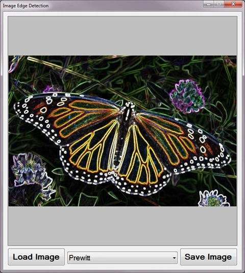
The following image is screenshot of the Image Edge Detection sample application in action:

Image Edge Detection Sample Application

Edge Detection

A good description of edge detection forms part of the on :

Edge detection is the name for a set of mathematical methods which aim at identifying points in a at which the changes sharply or, more formally, has discontinuities. The points at which image brightness changes sharply are typically organized into a set of curved line segments termed edges. The same problem of finding discontinuities in 1D signals is known as and the problem of finding signal discontinuities over time is known as . Edge detection is a fundamental tool in , and , particularly in the areas of and .

Image Convolution

A good introduction article  to can be found at: http://homepages.inf.ed.ac.uk/rbf/HIPR2/convolve.htm. From the article we learn the following:

Convolution is a simple mathematical operation which is fundamental to many common image processing operators. Convolution provides a way of `multiplying together’ two arrays of numbers, generally of different sizes, but of the same dimensionality, to produce a third array of numbers of the same dimensionality. This can be used in image processing to implement operators whose output pixel values are simple linear combinations of certain input pixel values.

In an image processing context, one of the input arrays is normally just a graylevel image. The second array is usually much smaller, and is also two-dimensional (although it may be just a single pixel thick), and is known as the kernel.

Single Matrix Convolution

The sample source code implements the ConvolutionFilter method, an targeting the class. The ConvolutionFilter method is intended to apply a user defined and optionally covert an to grayscale. The implementation as follows:

private static Bitmap ConvolutionFilter(Bitmap sourceBitmap, 
                                     double[,] filterMatrix, 
                                          double factor = 1, 
                                               int bias = 0, 
                                     bool grayscale = false) 
{
    BitmapData sourceData = 
                   sourceBitmap.LockBits(new Rectangle(0, 0,
                   sourceBitmap.Width, sourceBitmap.Height),
                                     ImageLockMode.ReadOnly, 
                                PixelFormat.Format32bppArgb);

byte[] pixelBuffer = new byte[sourceData.Stride * sourceData.Height];
byte[] resultBuffer = new byte[sourceData.Stride * sourceData.Height];
Marshal.Copy(sourceData.Scan0, pixelBuffer, 0, pixelBuffer.Length);
sourceBitmap.UnlockBits(sourceData);
if(grayscale == true) { float rgb = 0;
for(int k = 0; k < pixelBuffer.Length; k += 4) { rgb = pixelBuffer[k] * 0.11f; rgb += pixelBuffer[k + 1] * 0.59f; rgb += pixelBuffer[k + 2] * 0.3f;
pixelBuffer[k] = (byte)rgb; pixelBuffer[k + 1] = pixelBuffer[k]; pixelBuffer[k + 2] = pixelBuffer[k]; pixelBuffer[k + 3] = 255; } }
double blue = 0.0; double green = 0.0; double red = 0.0;
int filterWidth = filterMatrix.GetLength(1); int filterHeight = filterMatrix.GetLength(0);
int filterOffset = (filterWidth-1) / 2; int calcOffset = 0;
int byteOffset = 0;
for(int offsetY = filterOffset; offsetY < sourceBitmap.Height - filterOffset; offsetY++) { for(int offsetX = filterOffset; offsetX < sourceBitmap.Width - filterOffset; offsetX++) { blue = 0; green = 0; red = 0;
byteOffset = offsetY * sourceData.Stride + offsetX * 4;
for(int filterY = -filterOffset; filterY <= filterOffset; filterY++) { for(int filterX = -filterOffset; filterX <= filterOffset; filterX++) {
calcOffset = byteOffset + (filterX * 4) + (filterY * sourceData.Stride);
blue += (double)(pixelBuffer[calcOffset]) * filterMatrix[filterY + filterOffset, filterX + filterOffset];
green += (double)(pixelBuffer[calcOffset+1]) * filterMatrix[filterY + filterOffset, filterX + filterOffset];
red += (double)(pixelBuffer[calcOffset+2]) * filterMatrix[filterY + filterOffset, filterX + filterOffset]; } }
blue = factor * blue + bias; green = factor * green + bias; red = factor * red + bias;
if(blue > 255) { blue = 255;} else if(blue < 0) { blue = 0;}
if(green > 255) { green = 255;} else if(green < 0) { green = 0;}
if(red > 255) { red = 255;} else if(red < 0) { red = 0;}
resultBuffer[byteOffset] = (byte)(blue); resultBuffer[byteOffset + 1] = (byte)(green); resultBuffer[byteOffset + 2] = (byte)(red); resultBuffer[byteOffset + 3] = 255; } }
Bitmap resultBitmap = new Bitmap(sourceBitmap.Width, sourceBitmap.Height);
BitmapData resultData = resultBitmap.LockBits(new Rectangle(0, 0, resultBitmap.Width, resultBitmap.Height), ImageLockMode.WriteOnly, PixelFormat.Format32bppArgb);
Marshal.Copy(resultBuffer, 0, resultData.Scan0, resultBuffer.Length); resultBitmap.UnlockBits(resultData);
return resultBitmap; }

Horizontal and Vertical Matrix Convolution

The ConvolutionFilter has been overloaded to accept two matrices, representing a vertical and a horizontal . The implementation as follows:

public static Bitmap ConvolutionFilter(this Bitmap sourceBitmap,
                                        double[,] xFilterMatrix,
                                        double[,] yFilterMatrix,
                                              double factor = 1,
                                                   int bias = 0,
                                         bool grayscale = false)
{
    BitmapData sourceData = 
                   sourceBitmap.LockBits(new Rectangle(0, 0,
                   sourceBitmap.Width, sourceBitmap.Height),
                                     ImageLockMode.ReadOnly,
                                PixelFormat.Format32bppArgb);

byte[] pixelBuffer = new byte[sourceData.Stride * sourceData.Height];
byte[] resultBuffer = new byte[sourceData.Stride * sourceData.Height];
Marshal.Copy(sourceData.Scan0, pixelBuffer, 0, pixelBuffer.Length);
sourceBitmap.UnlockBits(sourceData);
if (grayscale == true) { float rgb = 0;
for (int k = 0; k < pixelBuffer.Length; k += 4) { rgb = pixelBuffer[k] * 0.11f; rgb += pixelBuffer[k + 1] * 0.59f; rgb += pixelBuffer[k + 2] * 0.3f;
pixelBuffer[k] = (byte)rgb; pixelBuffer[k + 1] = pixelBuffer[k]; pixelBuffer[k + 2] = pixelBuffer[k]; pixelBuffer[k + 3] = 255; } }
double blueX = 0.0; double greenX = 0.0; double redX = 0.0;
double blueY = 0.0; double greenY = 0.0; double redY = 0.0;
double blueTotal = 0.0; double greenTotal = 0.0; double redTotal = 0.0;
int filterOffset = 1; int calcOffset = 0;
int byteOffset = 0;
for (int offsetY = filterOffset; offsetY < sourceBitmap.Height - filterOffset; offsetY++) { for (int offsetX = filterOffset; offsetX < sourceBitmap.Width - filterOffset; offsetX++) { blueX = greenX = redX = 0; blueY = greenY = redY = 0;
blueTotal = greenTotal = redTotal = 0.0;
byteOffset = offsetY * sourceData.Stride + offsetX * 4;
for (int filterY = -filterOffset; filterY <= filterOffset; filterY++) { for (int filterX = -filterOffset; filterX <= filterOffset; filterX++) { calcOffset = byteOffset + (filterX * 4) + (filterY * sourceData.Stride);
blueX += (double) (pixelBuffer[calcOffset]) * xFilterMatrix[filterY + filterOffset, filterX + filterOffset];
greenX += (double) (pixelBuffer[calcOffset + 1]) * xFilterMatrix[filterY + filterOffset, filterX + filterOffset];
redX += (double) (pixelBuffer[calcOffset + 2]) * xFilterMatrix[filterY + filterOffset, filterX + filterOffset];
blueY += (double) (pixelBuffer[calcOffset]) * yFilterMatrix[filterY + filterOffset, filterX + filterOffset];
greenY += (double) (pixelBuffer[calcOffset + 1]) * yFilterMatrix[filterY + filterOffset, filterX + filterOffset];
redY += (double) (pixelBuffer[calcOffset + 2]) * yFilterMatrix[filterY + filterOffset, filterX + filterOffset]; } }
blueTotal = Math.Sqrt((blueX * blueX) + (blueY * blueY));
greenTotal = Math.Sqrt((greenX * greenX) + (greenY * greenY));
redTotal = Math.Sqrt((redX * redX) + (redY * redY));
if (blueTotal > 255) { blueTotal = 255; } else if (blueTotal < 0) { blueTotal = 0; }
if (greenTotal > 255) { greenTotal = 255; } else if (greenTotal < 0) { greenTotal = 0; }
if (redTotal > 255) { redTotal = 255; } else if (redTotal < 0) { redTotal = 0; }
resultBuffer[byteOffset] = (byte)(blueTotal); resultBuffer[byteOffset + 1] = (byte)(greenTotal); resultBuffer[byteOffset + 2] = (byte)(redTotal); resultBuffer[byteOffset + 3] = 255; } }
Bitmap resultBitmap = new Bitmap(sourceBitmap.Width, sourceBitmap.Height);
BitmapData resultData = resultBitmap.LockBits(new Rectangle(0, 0, resultBitmap.Width, resultBitmap.Height), ImageLockMode.WriteOnly, PixelFormat.Format32bppArgb);
Marshal.Copy(resultBuffer, 0, resultData.Scan0, resultBuffer.Length); resultBitmap.UnlockBits(resultData);
return resultBitmap; }

Original Sample Image

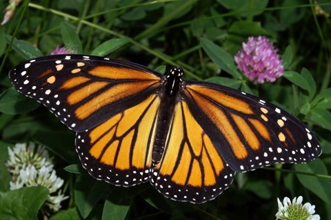
The original source image used to create all of the sample images in this article has been licensed under the Creative Commons Attribution-Share Alike 3.0 Unported, 2.5 Generic, 2.0 Generic and 1.0 Generic license. The original image is attributed to Kenneth Dwain Harrelson and can be downloaded from Wikipedia.

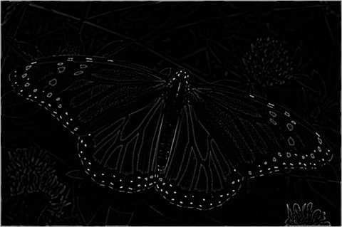
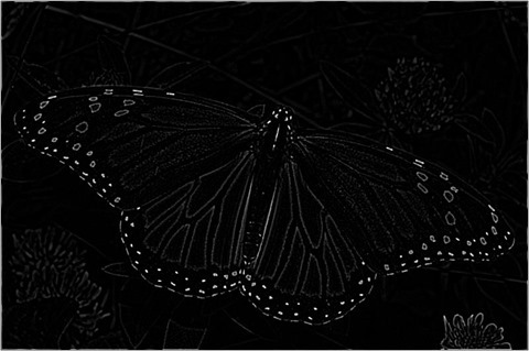
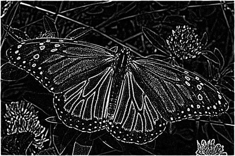
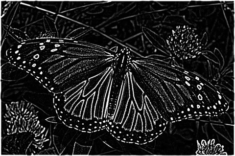
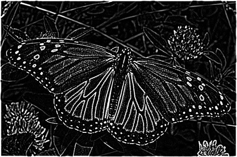
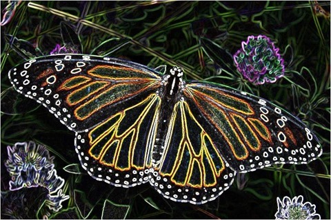
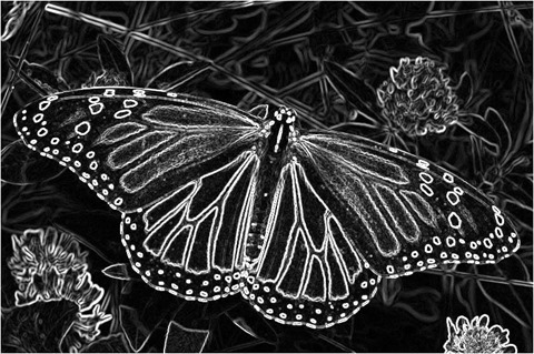
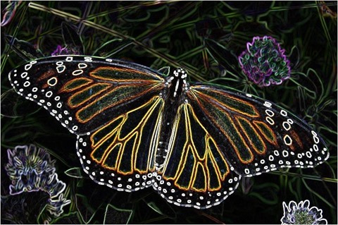
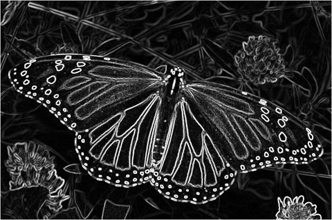
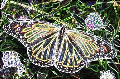
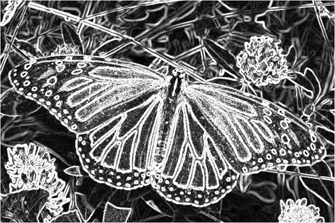
Monarch_In_May

Laplacian Edge Detection

The method of counts as one of the commonly used implementations. From we gain the following definition:

Discrete Laplace operator is often used in image processing e.g. in edge detection and motion estimation applications. The discrete Laplacian is defined as the sum of the second derivatives and calculated as sum of differences over the nearest neighbours of the central pixel.

A number of / variations may be applied with results ranging from slight to fairly pronounced. In the following sections of this article we explore two common implementations, 3×3 and 5×5.

Laplacian 3×3

When implementing a 3×3 you will notice little difference between colour and grayscale result .

public static Bitmap 
Laplacian3x3Filter(this Bitmap sourceBitmap, 
                      bool grayscale = true)
{
    Bitmap resultBitmap = 
           ExtBitmap.ConvolutionFilter(sourceBitmap, 
                                Matrix.Laplacian3x3,
                                  1.0, 0, grayscale);

return resultBitmap; }
public static double[,] Laplacian3x3
{ 
   get   
   { 
       return new double[,]
       { { -1, -1, -1, },  
         { -1,  8, -1, },  
         { -1, -1, -1, }, }; 
   } 
} 

Laplacian 3×3

Laplacian 3x3

Laplacian 3×3 Grayscale

Laplacian 3x3 Grayscale

Laplacian 5×5

The 5×5  produces result with a noticeable difference between colour and grayscale . The detected edges are expressed in a fair amount of fine detail, although the has a tendency to be sensitive to .

public static Bitmap 
Laplacian5x5Filter(this Bitmap sourceBitmap, 
                      bool grayscale = true)
{
    Bitmap resultBitmap =
           ExtBitmap.ConvolutionFilter(sourceBitmap, 
                                Matrix.Laplacian5x5,
                                  1.0, 0, grayscale);

return resultBitmap; }
public static double[,] Laplacian5x5 
{ 
    get   
    { 
       return new double[,]
       { { -1, -1, -1, -1, -1, },  
         { -1, -1, -1, -1, -1, },  
         { -1, -1, 24, -1, -1, },  
         { -1, -1, -1, -1, -1, },  
         { -1, -1, -1, -1, -1  } }; 
    } 
}

Laplacian 5×5

Laplacian 5x5

Laplacian 5×5 Grayscale

Laplacian 5x5 Grayscale

Laplacian of Gaussian

The (LoG) is a common variation of the filter. is intended to counter the noise sensitivity of the regular filter.

attempts to remove noise by implementing smoothing by means of a . In order to optimize performance we can calculate a single representing a and .

public static Bitmap 
LaplacianOfGaussian(this Bitmap sourceBitmap)
{
    Bitmap resultBitmap =
           ExtBitmap.ConvolutionFilter(sourceBitmap, 
                         Matrix.LaplacianOfGaussian, 
                                       1.0, 0, true);

return resultBitmap; }
public static double[,] LaplacianOfGaussian
{ 
    get   
    { 
        return new double[,]
        { {  0,  0, -1,  0,  0 },  
          {  0, -1, -2, -1,  0 },  
          { -1, -2, 16, -2, -1 }, 
          {  0, -1, -2, -1,  0 }, 
          {  0,  0, -1,  0,  0 } };
    } 
} 

Laplacian of Gaussian

Laplacian Of Gaussian

Laplacian (3×3) of Gaussian (3×3)

Different variations can be combined in an attempt to produce results best suited to the input . In this case we first apply a 3×3 followed by a 3×3 filter.

public static Bitmap 
Laplacian3x3OfGaussian3x3Filter(this Bitmap sourceBitmap)
{
    Bitmap resultBitmap =
           ExtBitmap.ConvolutionFilter(sourceBitmap, 
                                 Matrix.Gaussian3x3,
                                1.0 / 16.0, 0, true);

resultBitmap = ExtBitmap.ConvolutionFilter(resultBitmap, Matrix.Laplacian3x3, 1.0, 0, false);
return resultBitmap; }
public static double[,] Laplacian3x3
{ 
   get   
   { 
       return new double[,]
       { { -1, -1, -1, },  
         { -1,  8, -1, },  
         { -1, -1, -1, }, }; 
   } 
} 
public static double[,] Gaussian3x3
{ 
   get   
   { 
       return new double[,]
       { { 1, 2, 1, },  
         { 2, 4, 2, },  
         { 1, 2, 1, } }; 
   } 
} 

Laplacian 3×3 Of Gaussian 3×3

Laplacian 3x3 Of Gaussian 3x3

Laplacian (3×3) of Gaussian (5×5 – Type 1)

In this scenario we apply a variation of a 5×5 followed by a 3×3 filter.

public static Bitmap 
Laplacian3x3OfGaussian5x5Filter1(this Bitmap sourceBitmap)
{
    Bitmap resultBitmap = 
           ExtBitmap.ConvolutionFilter(sourceBitmap, 
                            Matrix.Gaussian5x5Type1,
                               1.0 / 159.0, 0, true);

resultBitmap = ExtBitmap.ConvolutionFilter(resultBitmap, Matrix.Laplacian3x3, 1.0, 0, false);
return resultBitmap; }
public static double[,] Laplacian3x3
{ 
   get   
   { 
       return new double[,]
       { { -1, -1, -1, },  
         { -1,  8, -1, },  
         { -1, -1, -1, }, }; 
   } 
} 
public static double[,] Gaussian5x5Type1 
{ 
   get   
   { 
       return new double[,]   
       { { 2, 04, 05, 04, 2 },  
         { 4, 09, 12, 09, 4 },  
         { 5, 12, 15, 12, 5 }, 
         { 4, 09, 12, 09, 4 }, 
         { 2, 04, 05, 04, 2 }, }; 
   } 
} 

Laplacian 3×3 Of Gaussian 5×5 – Type 1

Laplacian 3x3 Of Gaussian 5x5 Type1

Laplacian (3×3) of Gaussian (5×5 – Type 2)

The following implementation is very similar to the previous implementation. Applying a variation of a 5×5 results in slight differences.

public static Bitmap 
Laplacian3x3OfGaussian5x5Filter2(this Bitmap sourceBitmap)
{
    Bitmap resultBitmap = 
           ExtBitmap.ConvolutionFilter(sourceBitmap, 
                            Matrix.Gaussian5x5Type2,
                               1.0 / 256.0, 0, true);

resultBitmap = ExtBitmap.ConvolutionFilter(resultBitmap, Matrix.Laplacian3x3, 1.0, 0, false);
return resultBitmap; }
public static double[,] Laplacian3x3
{ 
   get   
   { 
       return new double[,]
       { { -1, -1, -1, },  
         { -1,  8, -1, },  
         { -1, -1, -1, }, }; 
   } 
} 
public static double[,] Gaussian5x5Type2 
{ 
   get   
   {
       return new double[,]  
       { {  1,   4,  6,  4,  1 },  
         {  4,  16, 24, 16,  4 },  
         {  6,  24, 36, 24,  6 }, 
         {  4,  16, 24, 16,  4 }, 
         {  1,   4,  6,  4,  1 }, }; 
   }
} 

Laplacian 3×3 Of Gaussian 5×5 – Type 2

Laplacian 3x3 Of Gaussian 5x5 Type2

Laplacian (5×5) of Gaussian (3×3)

This variation of the filter implements a 3×3 , followed by a 5×5 . The resulting appears significantly brighter when compared to a 3×3 .

public static Bitmap 
Laplacian5x5OfGaussian3x3Filter(this Bitmap sourceBitmap)
{
    Bitmap resultBitmap = 
           ExtBitmap.ConvolutionFilter(sourceBitmap, 
                                 Matrix.Gaussian3x3,
                                1.0 / 16.0, 0, true);

resultBitmap = ExtBitmap.ConvolutionFilter(resultBitmap, Matrix.Laplacian5x5, 1.0, 0, false);
return resultBitmap; }
public static double[,] Laplacian5x5 
{ 
    get   
    { 
       return new double[,]
       { { -1, -1, -1, -1, -1, },  
         { -1, -1, -1, -1, -1, },  
         { -1, -1, 24, -1, -1, },  
         { -1, -1, -1, -1, -1, },  
         { -1, -1, -1, -1, -1  } }; 
    } 
}
public static double[,] Gaussian3x3
{ 
   get   
   { 
       return new double[,]
       { { 1, 2, 1, },  
         { 2, 4, 2, },  
         { 1, 2, 1, } }; 
   } 
} 

Laplacian 5×5 Of Gaussian 3×3

Laplacian 5x5 Of Gaussian 3x3

Laplacian (5×5) of Gaussian (5×5 – Type 1)

Implementing a larger results in a higher degree of smoothing, equating to less .

public static Bitmap 
Laplacian5x5OfGaussian5x5Filter1(this Bitmap sourceBitmap)
{
    Bitmap resultBitmap = 
           ExtBitmap.ConvolutionFilter(sourceBitmap, 
                            Matrix.Gaussian5x5Type1,
                               1.0 / 159.0, 0, true);

resultBitmap = ExtBitmap.ConvolutionFilter(resultBitmap, Matrix.Laplacian5x5, 1.0, 0, false);
return resultBitmap; }
public static double[,] Laplacian5x5 
{ 
    get   
    { 
       return new double[,]
       { { -1, -1, -1, -1, -1, },  
         { -1, -1, -1, -1, -1, },  
         { -1, -1, 24, -1, -1, },  
         { -1, -1, -1, -1, -1, },  
         { -1, -1, -1, -1, -1  } }; 
    } 
}
public static double[,] Gaussian5x5Type1 
{ 
   get   
   { 
       return new double[,]   
       { { 2, 04, 05, 04, 2 },  
         { 4, 09, 12, 09, 4 },  
         { 5, 12, 15, 12, 5 }, 
         { 4, 09, 12, 09, 4 }, 
         { 2, 04, 05, 04, 2 }, }; 
   } 
} 

Laplacian 5×5 Of Gaussian 5×5 – Type 1

Laplacian 5x5 Of Gaussian 5x5 Type1

Laplacian (5×5) of Gaussian (5×5 – Type 2)

The variation of most applicable when implementing a filter depends on expressed by a source . In this scenario the first variations (Type 1) appears to result in less .

public static Bitmap 
Laplacian5x5OfGaussian5x5Filter2(this Bitmap sourceBitmap)
{
    Bitmap resultBitmap = 
           ExtBitmap.ConvolutionFilter(sourceBitmap, 
                            Matrix.Gaussian5x5Type2, 
                               1.0 / 256.0, 0, true);

resultBitmap = ExtBitmap.ConvolutionFilter(resultBitmap, Matrix.Laplacian5x5, 1.0, 0, false);
return resultBitmap; }
public static double[,] Laplacian5x5 
{ 
    get   
    { 
       return new double[,]
       { { -1, -1, -1, -1, -1, },  
         { -1, -1, -1, -1, -1, },  
         { -1, -1, 24, -1, -1, },  
         { -1, -1, -1, -1, -1, },  
         { -1, -1, -1, -1, -1  } }; 
    } 
}
public static double[,] Gaussian5x5Type2 
{ 
   get   
   {
       return new double[,]  
       { {  1,   4,  6,  4,  1 },  
         {  4,  16, 24, 16,  4 },  
         {  6,  24, 36, 24,  6 }, 
         {  4,  16, 24, 16,  4 }, 
         {  1,   4,  6,  4,  1 }, }; 
   }
} 

Laplacian 5×5 Of Gaussian 5×5 – Type 2

Laplacian 5x5 Of Gaussian 5x5 Type2

Sobel Edge Detection

is another common implementation of . We gain the following from :

The Sobel operator is used in , particularly within edge detection algorithms. Technically, it is a , computing an approximation of the of the image intensity function. At each point in the image, the result of the Sobel operator is either the corresponding gradient vector or the norm of this vector. The Sobel operator is based on convolving the image with a small, separable, and integer valued filter in horizontal and vertical direction and is therefore relatively inexpensive in terms of computations. On the other hand, the gradient approximation that it produces is relatively crude, in particular for high frequency variations in the image.

Unlike the filters discussed earlier, filter results differ significantly when comparing colour and grayscale . The filter tends to be less sensitive to compared to the filter. The detected edge lines are not as finely detailed/granular as the detected edge lines resulting from filters.

public static Bitmap 
Sobel3x3Filter(this Bitmap sourceBitmap, 
                  bool grayscale = true)
{
    Bitmap resultBitmap =
           ExtBitmap.ConvolutionFilter(sourceBitmap, 
                          Matrix.Sobel3x3Horizontal, 
                            Matrix.Sobel3x3Vertical, 
                                  1.0, 0, grayscale);

return resultBitmap; }
 
public static double[,] Sobel3x3Horizontal
{ 
   get   
   {
       return new double[,]  
       { { -1,  0,  1, },  
         { -2,  0,  2, },  
         { -1,  0,  1, }, }; 
   } 
} 
public static double[,] Sobel3x3Vertical 
{ 
   get   
   { 
       return new double[,]  
       { {  1,  2,  1, },  
         {  0,  0,  0, },  
         { -1, -2, -1, }, }; 
   } 
}

Sobel 3×3

Sobel 3x3

Sobel 3×3 Grayscale

Sobel 3x3 Grayscale

Prewitt Edge Detection

As with the other methods of discussed in this article the method is also a fairly common implementation. From we gain the following quote:

The Prewitt operator is used in , particularly within algorithms. Technically, it is a , computing an approximation of the of the image intensity function. At each point in the image, the result of the Prewitt operator is either the corresponding gradient vector or the norm of this vector. The Prewitt operator is based on convolving the image with a small, separable, and integer valued filter in horizontal and vertical direction and is therefore relatively inexpensive in terms of computations. On the other hand, the gradient approximation which it produces is relatively crude, in particular for high frequency variations in the image. The Prewitt operator was developed by Judith M. S. Prewitt.

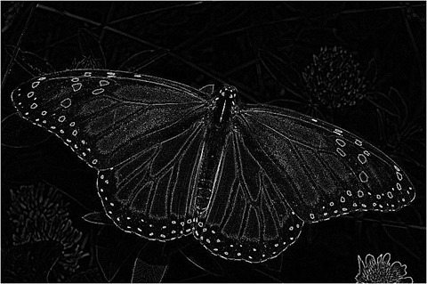
In simple terms, the operator calculates the of the image intensity at each point, giving the direction of the largest possible increase from light to dark and the rate of change in that direction. The result therefore shows how "abruptly" or "smoothly" the image changes at that point, and therefore how likely it is that that part of the image represents an edge, as well as how that edge is likely to be oriented. In practice, the magnitude (likelihood of an edge) calculation is more reliable and easier to interpret than the direction calculation.

Similar to the filter, resulting express a significant difference when comparing colour and grayscale .

public static Bitmap 
PrewittFilter(this Bitmap sourceBitmap, 
                 bool grayscale = true)
{
    Bitmap resultBitmap =
           ExtBitmap.ConvolutionFilter(sourceBitmap, 
                        Matrix.Prewitt3x3Horizontal, 
                          Matrix.Prewitt3x3Vertical, 
                                  1.0, 0, grayscale);

return resultBitmap; }
public static double[,] Prewitt3x3Horizontal 
{ 
   get   
   { 
       return new double[,]  
       { { -1,  0,  1, },  
         { -1,  0,  1, },  
         { -1,  0,  1, }, }; 
   } 
} 
  
public static double[,] Prewitt3x3Vertical 
{ 
   get   
   { 
       return new double[,]  
       { {  1,  1,  1, },  
         {  0,  0,  0, },  
         { -1, -1, -1, }, }; 
   }
}

Prewitt

Prewitt

Prewitt Grayscale

Prewitt Grayscale

Kirsch Edge Detection

The method is often implemented in the form of Compass . In the following scenario we only implement two components: Horizontal and Vertical. Resulting tend to have a high level of brightness.

public static Bitmap 
KirschFilter(this Bitmap sourceBitmap, 
                bool grayscale = true)
{
    Bitmap resultBitmap =
           ExtBitmap.ConvolutionFilter(sourceBitmap, 
                         Matrix.Kirsch3x3Horizontal, 
                           Matrix.Kirsch3x3Vertical, 
                                  1.0, 0, grayscale);

return resultBitmap; }
public static double[,] Kirsch3x3Horizontal 
{ 
   get   
   {
       return new double[,]  
       { {  5,  5,  5, },  
         { -3,  0, -3, },  
         { -3, -3, -3, }, }; 
   } 
} 
public static double[,] Kirsch3x3Vertical
{ 
   get   
   { 
       return new double[,]  
       { {  5, -3, -3, },  
         {  5,  0, -3, },  
         {  5, -3, -3, }, }; 
   } 
}

Kirsch

Kirsch 

Kirsch Grayscale

Kirsch Grayscale

Related Articles and Feedback

Feedback and questions are always encouraged. If you know of an alternative implementation or have ideas on a more efficient implementation please share in the comments section.

I’ve published a number of articles related to imaging and images of which you can find URL links here:


Dewald Esterhuizen

Blog Stats

  • 869,800 hits

Enter your email address to follow and receive notifications of new posts by email.

Join 228 other subscribers

Archives

RSS SoftwareByDefault on MSDN

  • An error has occurred; the feed is probably down. Try again later.