Archive for the 'Graphics' Category

C# How to: Min/Max Edge Detection

Article Purpose

This article serves as a detailed discussion on implementing  through maximum and minimum value subtraction. Additional concepts illustrated in this article include implementing a and RGB conversion.

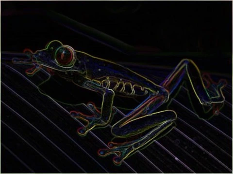
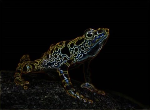
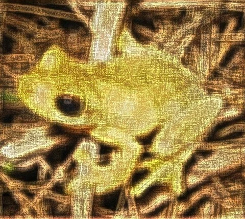
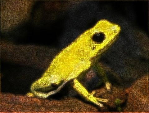
Frog Filter 3×3 Smoothed

Frog Filter 3x3 Smoothed

Sample Source Code

This article is accompanied by a sample source code Visual Studio project which is available for download .

Min Max Edge Detection Sample Source Code

Using the Sample Application

This article’s accompanying sample source code includes a based sample application. The sample application provides an implementation of the concepts explored by this article. Concepts discussed can be easily replicated and tested by using the sample application.

Source/input files can be specified from the local system when clicking the Load Image button. Additionally users also have the option to save resulting filtered by clicking the Save Image button.

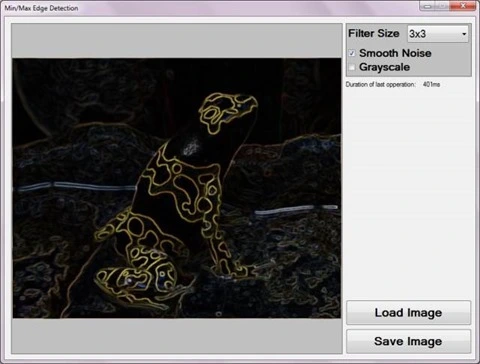
The sample application user interface enables the user  to specify three filter configuration values. These values serve as input parameters to the Min/Max Edge Detection Filter and can be described as follows:

  • Filter Size – Determines the number of surrounding to consider when calculating the minimum and maximum pixel values. This value equates to the size of a pixel’s neighbourhood of pixels. When gradient edges expressed in a source image requires a higher or lower level of expression in result images the filter size value should be adjusted. Higher Filter Size values result in gradient edges being expressed at greater intensity levels in resulting images. Inversely, lower Filter Size values delivers the opposite result of gradient edges being expressed at lesser intensity levels.
  • Smooth Noise – when present in source images, can to varying degrees affect the Min/Max Edge Detection Filter’s accuracy in calculating gradient edges. In order to reduce the negative affects of source image noise an image smoothing filter may be implemented. Smoothing out image noise requires additional filter processing and therefore requires additional computation time. If source images reflect minor or no image noise, additional image smoothing may be excluded to reduce filter processing duration.
  • Grayscale – When required, result images can be expressed in grayscale through configuring this value.

The following image represents a screenshot of the Min/Max Edge Detection Sample application in action.

Min Max Edge Detection Sample Application

Min/Max

The method of illustrated in this article can be classified as a variation of commonly implemented edge detection methods. expressed within a source can be determined through the presence of sudden and significant changes in gradient levels that occur within a small/limited perimeter.

As a means to determine gradient level changes the Min/Max Edge Detection algorithm performs inspection, comparing maximum and minimum colour channel values. Should the difference between maximum and minimum colour values be significant, it would be an indication of a significant change in gradient level within the being inspected.

Image noise represents interference in relation to regular gradient level expression. Image noise does not signal the presence of an , although could potentially result in incorrectly determining image edge presence. Image noise and the negative impact thereof can be significantly reduced when applying image smoothing, also sometimes referred to as . The Min/Max Edge Detection algorithm makes provision for optional image smoothing implemented in the form of a filter.

The following sections provide more detail regarding the concepts introduced in this section, pixel neighbourhood and median filter.

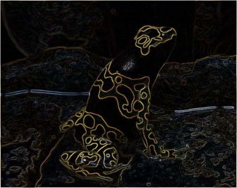
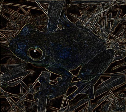
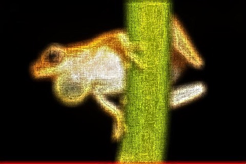
Frog Filter 3×3 Smoothed

Frog Filter 3x3 Smoothed

Pixel Neighbourhood

A refers to a set of pixels, all of which are related through location coordinates. The width and height of a must be equal, in other words, a pixel neighbourhood can only be square. Additionally, the width/height of a pixel neighbourhood must be an uneven value. When inspecting a pixel’s neighbouring pixels, the pixel being inspected will always be located at the exact center of the . Only when a pixel neighbourhood’s width/height are an uneven value can such a have an exact center pixel. Each pixel represented in an has a different set of neighbours, some neighbours overlap, but no two pixels have the exact same neighbours. A pixel’s neighbouring pixels can be determined when considering the pixel to be at the center of a block of pixels, extending half the neighbourhood size less one in horizontal, vertical and diagonal directions.

Median Filter

In context of this article and the Min/Max Edge Detection filter, median filtering has been implemented as a means to reduce source image noise. From the we gain the following quote:

In statistics and probability theory, the median is the number separating the higher half of a data sample, a population, or a probability distribution, from the lower half. The median of a finite list of numbers can be found by arranging all the observations from lowest value to highest value and picking the middle one (e.g., the median of {3, 3, 5, 9, 11} is 5).

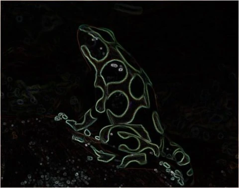
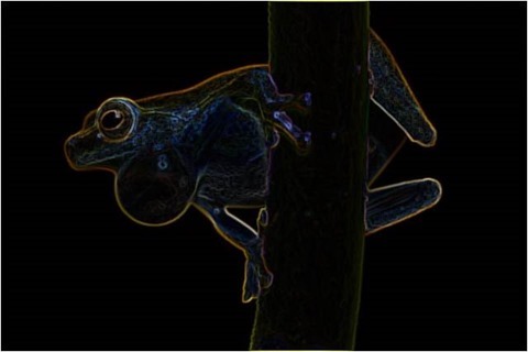
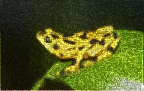
Frog Filter 3×3 Smoothed

Frog2_Filter3x3_Smoothed

The application of a filter is based in the concept of as discussed earlier. The implementation steps required when applying a median filter can be described as follows:

  1. Iterate every pixel. The of each pixel in a source image needs to be determined and inspected.
  2. Order/Sort pixel neighbourhood values. Once a pixel neighbourhood for a specific pixel has been determined the values expressed by all the pixels in that neighbourhood needs to be sorted or ordered according to value.
  3. Determine midpoint value. In relation to the sorted values, the value positioned exactly halfway between first and last value needs to be determined. As an example, if a pixel neighbourhood contains a total of nine pixels, the midpoint would be at position number five, which is four positions from the first and last value inclusive. The midpoint value in a sorted range of neighbourhood pixel values, is the median value of that pixel neighbourhood’s values.

The median filter should not be confused with the . A median will always be a midpoint value from a sorted value range, whereas a value is equal to the calculated average of a value range. The median filter has the characteristic of reducing image noise whilst still preserving . The mean filter will also reduce image noise, but will do so through generalized , also referred to as , which does not preserve .

Note that when applying a median filter to RGB colour images values need to be determined per individual colour channel.

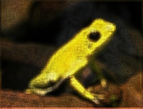
Frog Filter 3×3 Smoothed

Frog Filter 3x3 Smoothed

Min/Max Edge Detection Algorithm

based in a min/max approach requires relatively few steps, which can be combined in source code implementations to be more efficient from a computational/processing perspective. A higher level logical definition of the steps required can be described as follows:

  1. Image Noise Reduction – If image is required apply a filter to the source image.
  2. Iterate through all of the pixels contained within an .
  3. For each pixel being iterated, determine the neighbouring pixels. The size will be determined by the specified filter size.
  4. Determine the Minimum and Maximum pixel value expressed within the pixel neighbourhood.
  5. Subtract the Minimum from the Maximum value and assign the result to the pixel currently being iterated.
  6. Apply Grayscale conversion to the pixel currently being iterated, only if grayscale conversion had been configured.

Implementing a Min/Max Edge Detection Filter

The source code implementation of the Min/Max Edge Detection Filter declares two methods, a filter method and an method. A median filter and edge detection filter cannot be processed simultaneously. When applying a filter, the median value of a pixel neighbourhood determined from a source image should be expressed in a separate result image. The original source image should not be altered whilst inspecting pixel neighbourhoods and calculating median values. Only once all pixel values in the result image has been set, can the result image serve as a source image to an filter method.

The following code snippet provides the source code definition of the MedianFilter method.

private static byte[] MedianFilter(this byte[] pixelBuffer,
                                    int imageWidth,
                                    int imageHeight,
                                    int filterSize)
{
    byte[] resultBuffer = new byte[pixelBuffer.Length];

    int filterOffset = (filterSize - 1) / 2;
    int calcOffset = 0;
    int stride = imageWidth * pixelByteCount;

    int byteOffset = 0;
    var neighbourCount = filterSize * filterSize;
    int medianIndex = neighbourCount / 2;

    var blueNeighbours = new byte[neighbourCount];
    var greenNeighbours = new byte[neighbourCount];
    var redNeighbours = new byte[neighbourCount];

    for (int offsetY = filterOffset; offsetY <
        imageHeight - filterOffset; offsetY++)
    {
        for (int offsetX = filterOffset; offsetX <
            imageWidth - filterOffset; offsetX++)
        {
            byteOffset = offsetY *
                            stride +
                            offsetX * pixelByteCount;

            for (int filterY = -filterOffset, neighbour = 0;
                filterY <= filterOffset; filterY++)
            {
                for (int filterX = -filterOffset;
                    filterX <= filterOffset; filterX++, neighbour++)
                {
                    calcOffset = byteOffset +
                                    (filterX * pixelByteCount) +
                                    (filterY * stride);

                    blueNeighbours[neighbour] = pixelBuffer[calcOffset];
                    greenNeighbours[neighbour] = pixelBuffer[calcOffset + greenOffset];
                    redNeighbours[neighbour] = pixelBuffer[calcOffset + redOffset];
                }
            }

            Array.Sort(blueNeighbours);
            Array.Sort(greenNeighbours);
            Array.Sort(redNeighbours);

            resultBuffer[byteOffset] = blueNeighbours[medianIndex];
            resultBuffer[byteOffset + greenOffset] = greenNeighbours[medianIndex];
            resultBuffer[byteOffset + redOffset] = redNeighbours[medianIndex];
            resultBuffer[byteOffset + alphaOffset] = maxByteValue;
        }
    }

    return resultBuffer;
}

Notice the definition of three separate arrays, each intended to represent a ’s pixel values related to a specific colour channel. Each neighbourhood colour channel byte array needs to be sorted according to value. The value located at the array index exactly halfway from the start and the end of the array represents the value. When a median value has been determined, the result buffer pixel related to the source buffer pixel in terms of XY Location needs to be set.

Frog Filter 3×3 Smoothed

Frog Filter 3x3 Smoothed

The sample source code defines two overloaded versions of an edge detection method. The first version is defined as an targeting the class. A FilterSize parameter is the only required parameter, intended to specify width/height. In addition, when invoking this method  optional parameters may be specified. When image noise reduction should be implemented the smoothNoise parameter should be defined as true. If resulting images are required in grayscale the last parameter, , should reflect true. The following code snippet provides the definition of the MinMaxEdgeDetection method.

public static Bitmap MinMaxEdgeDetection(this Bitmap sourceBitmap,
                                            int filterSize, 
                                            bool smoothNoise = false, 
                                            bool grayscale = false)
{
    return sourceBitmap.ToPixelBuffer()
                        .MinMaxEdgeDetection(sourceBitmap.Width, 
                                            sourceBitmap.Height, 
                                            filterSize,
                                            smoothNoise,
                                            grayscale)
                        .ToBitmap(sourceBitmap.Width, 
                                    sourceBitmap.Height);
}

The MinMaxEdgeDetection method as expressed above essentially acts as a wrapper method, invoking the overloaded version of this method, performing mapping between objects and byte array pixel buffers.

An overloaded version of the MinMaxEdgeDetection method performs all of the tasks required in through means of minimum maximum value subtraction. The method definition as provided by the following code snippet.

private static byte[] MinMaxEdgeDetection(this byte[] sourceBuffer,
                                          int imageWidth,
                                          int imageHeight,
                                          int filterSize,
                                          bool smoothNoise = false,
                                          bool grayscale = false)
{
    byte[] pixelBuffer = sourceBuffer;

    if (smoothNoise)
    {
        pixelBuffer = sourceBuffer.MedianFilter(imageWidth, 
                                                imageHeight, 
                                                filterSize);
    }

    byte[] resultBuffer = new byte[pixelBuffer.Length];

    int filterOffset = (filterSize - 1) / 2;
    int calcOffset = 0;
    int stride = imageWidth * pixelByteCount;

    int byteOffset = 0;

    byte minBlue = 0, minGreen = 0, minRed = 0;
    byte maxBlue = 0, maxGreen = 0, maxRed = 0;

    for (int offsetY = filterOffset; offsetY <
        imageHeight - filterOffset; offsetY++)
    {
        for (int offsetX = filterOffset; offsetX <
            imageWidth - filterOffset; offsetX++)
        {
            byteOffset = offsetY *
                            stride +
                            offsetX * pixelByteCount;

            minBlue = maxByteValue;
            minGreen = maxByteValue;
            minRed = maxByteValue;

            maxBlue = minByteValue;
            maxGreen = minByteValue;
            maxRed = minByteValue;

            for (int filterY = -filterOffset;
                filterY <= filterOffset; filterY++)
            {
                for (int filterX = -filterOffset;
                    filterX <= filterOffset; filterX++)
                {
                    calcOffset = byteOffset +
                                    (filterX * pixelByteCount) +
                                    (filterY * stride);

                    minBlue = Math.Min(pixelBuffer[calcOffset], minBlue);
                    maxBlue = Math.Max(pixelBuffer[calcOffset], maxBlue);

                    minGreen = Math.Min(pixelBuffer[calcOffset + greenOffset], minGreen);
                    maxGreen = Math.Max(pixelBuffer[calcOffset + greenOffset], maxGreen);

                    minRed = Math.Min(pixelBuffer[calcOffset + redOffset], minRed);
                    maxRed = Math.Max(pixelBuffer[calcOffset + redOffset], maxRed);
                }
            }

            if (grayscale)
            {
                resultBuffer[byteOffset] = ByteVal((maxBlue - minBlue) * 0.114 + 
                                                    (maxGreen - minGreen) * 0.587 + 
                                                    (maxRed - minRed) * 0.299);

                resultBuffer[byteOffset + greenOffset] = resultBuffer[byteOffset];
                resultBuffer[byteOffset + redOffset] = resultBuffer[byteOffset];
                resultBuffer[byteOffset + alphaOffset] = maxByteValue;
            }
            else
            {
                resultBuffer[byteOffset] = (byte)(maxBlue - minBlue);
                resultBuffer[byteOffset + greenOffset] = (byte)(maxGreen - minGreen);
                resultBuffer[byteOffset + redOffset] = (byte)(maxRed - minRed);
                resultBuffer[byteOffset + alphaOffset] = maxByteValue;
            }
        }
    }

    return resultBuffer;
}

As discussed earlier, image if required should be the first task performed. Based on parameter value the method applies a filter to the source image buffer.

When iterating a a comparison is performed between the currently iterated neighbouring pixel’s value and the previously determined minimum and maximum values.

When the grayscale method parameter reflects true, a grayscale algorithm is applied to the difference between the determined maximum and minimum values.

Should the grayscale method parameter reflect false, grayscale algorithm logic will not execute. Instead, the result obtained from subtracting the determined minimum and maximum values are assigned to the relevant pixel and colour channel on the result buffer image.

Frog Filter 3×3 Smoothed

Frog Filter 3x3 Smoothed

Sample Images

This article features several sample images provided as examples. All sample images were created using the sample application. All of the original source images used in generating sample images have been licensed by their respective authors to allow for reproduction here. The following section lists each original source image and related license and copyright details.

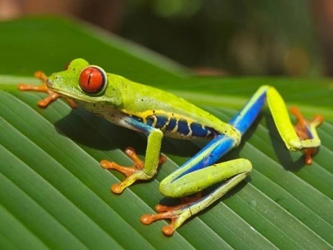
Red-eyed Tree Frog (Agalychnis callidryas), photographed near Playa Jaco in Costa Rica © 2007 Careyjamesbalboa (Carey James Balboa) has been released into the public domain by the author.

Red_eyed_tree_frog_edit2

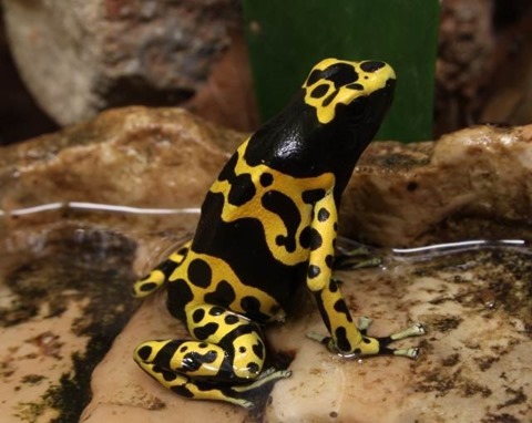
Yellow-Banded Poison Dart Frog © 2013 H. Krisp  is used here under a Creative Commons Attribution 3.0 Unported license.

Bumblebee_Poison_Frog_Dendrobates_leucomelas

Green and Black Poison Dart Frog © 2011 H. Krisp  is used here under a Creative Commons Attribution 3.0 Unported license.

Dendrobates-auratus-goldbaumsteiger

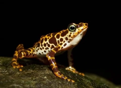
Atelopus certus calling male © 2010 Brian Gratwicke  is used here under a Creative Commons Attribution 2.0 Generic license.

Atelopus_certus_calling_male_edit

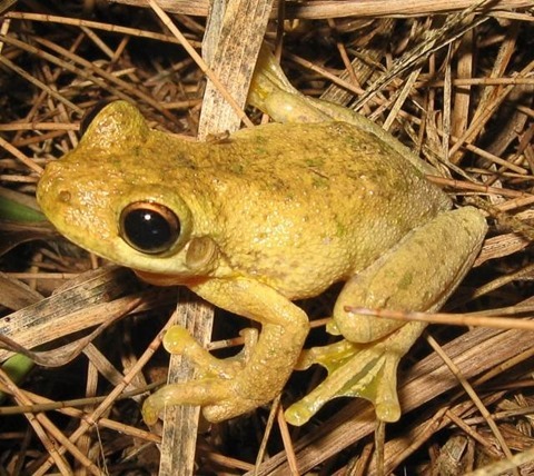
Tyler’s Tree Frog (Litoria tyleri) © 2006 LiquidGhoul  has been released into the public domain by the author.

Litoria_tyleri

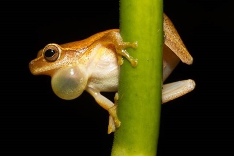
Dendropsophus microcephalus © 2010 Brian Gratwicke  is used here under a Creative Commons Attribution 2.0 Generic license.

Dendropsophus_microcephalus_-_calling_male_(Cope,_1886)

Related Articles and Feedback

Feedback and questions are always encouraged. If you know of an alternative implementation or have ideas on a more efficient implementation please share in the comments section.

I’ve published a number of articles related to imaging and images of which you can find URL links here:

C# How to: Standard Deviation Edge Detection

Article Purpose

This article explores detection implemented through computing neighbourhood on RGB  . The main sections of this article consists of a detailed explanation of the concepts related to the standard deviation edge detection algorithm and an in-depth discussion and a practical implementation through source code.

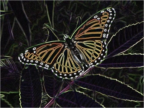
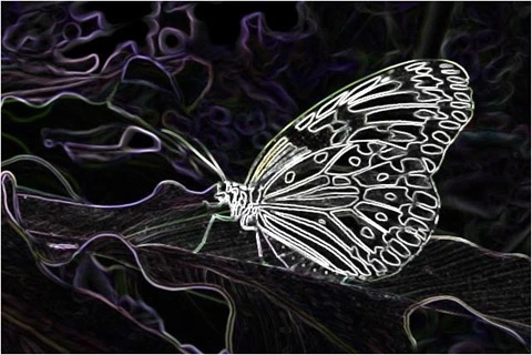
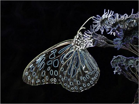
Butterfly Filter 3×3 Factor 5.0

Butterfly Filter 3x3 Factor 5.0

Sample Source Code

This article is accompanied by a sample source code Visual Studio project which is available for download .

Using the Sample Application

This article’s accompanying sample source code includes a based sample application. The sample application provides an implementation of the concepts explored by this article. Concepts discussed can be easily replicated and tested by using the sample application.

Source/input files can be specified from the local system when clicking the Load Image button. Additionally users also have the option to save resulting filtered by clicking the Save Image button.

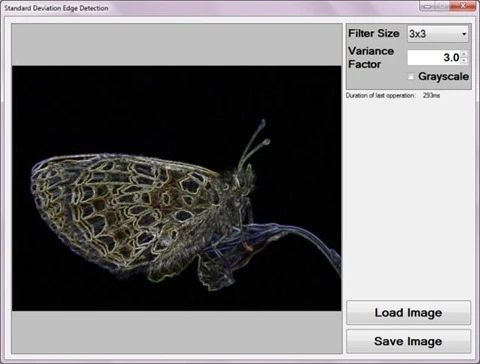
The sample application user interface exposes three filter configuration values to the end user in the form of predefined filter size values, a output flag and a factor. End users can configure whether filtered result images should express using source colour values or in . The filter size value specified by the user determines the number of included when calculating values.

Filter size has a direct correlation to the extend at which gradient edges will be represented in resulting images. Faint edge values require larger filter size values in order to be expressed in a resulting output image. Larger filter size values require additional computation and would thus have a longer completion time when compared to smaller filter size values.

The following screenshot captures the Standard Deviation Edge Detection sample application in action.

Standard Deviation Edge Detection Screenshot

Standard Deviation

can be achieved through a variety of methods, each associated with particular benefits and trade offs. This article is focussed on through implementing calculations on a neighbourhood.

Pixel Neighbourhood

A pixel neighbourhood refers to a set of pixels, all of which are related through location coordinates. The width and height of a pixel neighbourhood must be equal, in other words, a pixel neighbourhood can only be square. Additionally, the width/height of a pixel neighbourhood must be an uneven value. When inspecting a pixel’s neighbouring pixels, the pixel being inspected will always be located at the exact center of the pixel neighbourhood. Only when a pixel neighbourhood’s width/height are an uneven value can such a pixel neighbourhood have an exact center pixel. Each pixel represented in an has a different set of neighbours, some neighbours overlap, but no two pixels have the exact same neighbours. A pixel’s neighbouring pixels can be determined when considering the pixel to be at the center of a block of pixels, extending half the neighbourhood size less one in horizontal, vertical and diagonal directions.

Butterfly Filter 3×3 Factor 5

Butterfly Filter 3x3 Factor 5

Pixel Neighbourhood Mean value

value calculation forms a core part in calculating . The mean value from a set of values could be considered equivalent to the value set’s average value. The average of a set of  values can be calculated as the sum total of all the values in a set, divided by the number of values in the set.

Standard Deviation

From the page we gain the following quote:

In statistics, the standard deviation (SD, also represented by the Greek letter sigma, σ for the population standard deviation or s for the sample standard deviation) is a measure that is used to quantify the amount of variation or dispersion of a set of data values. A standard deviation close to 0 indicates that the data points tend to be very close to the (also called the expected value) of the set, while a high standard deviation indicates that the data points are spread out over a wider range of values

A pixel neighbourhood’s can indicate whether a significant change in image gradient is present in a neighbourhood. A large value is an indication that the neighbourhood’s pixel values could be spread far from the calculated . Inversely, a small will indicate that the neighbourhood’s pixel values are closer to the calculated . A sudden change in image gradient will equate to a large standard deviation.

Steps required in calculating can be described as follows:

  1. Calculate the Mean value. Calculate the sum of all pixels in a pixel neighbourhood then divide the sum total using the number of pixels contained in a neighbourhood. In essence calculating the mean value should be seen as calculating the average of all the pixels in a neighbourhood.
  2. Calculate combined Variance using value. Subtract the mean value from each pixel in the neighbourhood, the result should be squared and added to a sum total. should then be calculated as the calculated mean subtracted squared pixel value divided using the number of pixels in a neighbourhood.
  3. Calculate as the Variance square root.

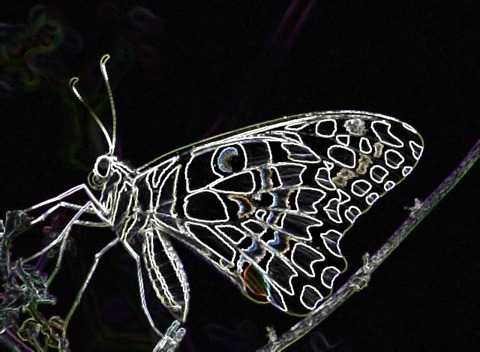
Butterfly Filter 3×3 Factor 5

Butterfly Filter 3x3 Factor 5

Standard Deviation Edge Detection Algorithm

The standard deviation edge detection algorithm is based in the concept of , providing additional capabilities. The algorithm allows for a more prominent expression of through means of a  variance factor. Calculated values can be increased or decreased when implementing a variance factor. When variances are less significant, resulting images will express gradient edges at faint/low intensity levels. Providing a factor will result in output images expressing gradient edges at a higher intensity.

factor and filter size should not be confused. When source gradient edges are expressed at low intensities, higher filter sizes would result in those low intensity source edges to be expressed in resulting images. In a scenario where high intensity gradient edges from a source are expressed in resulting images at low intensities, a higher factor would increase resulting edge intensity.

The following list provides a summary of the steps required  to implement the algorithm:

  1. Iterate through all of the pixels contained within an .
  2. For each pixel being iterated, determine the neighbouring pixels. The pixel neighbourhood size will be determined by the specified filter size.
  3. Calculate the Mean value of the current pixel neighbourhood.
  4. Calculate the Variance. Subtract the value from each neighbourhood pixel, the result should be squared and summed to a total value. Finally, the variance total value should be divided by the number of pixels that make up the pixel  neighbourhood. If a variance factor had been specified, the calculated variance value should be multiplied against it and the result assigned as the new calculated value.
  5. Calculate the Standard Deviation. Once the has been calculated the can be expressed as the square root of the calculated value. The value should be assigned to the result buffer pixel relating to the source buffer pixel currently being iterated.

It is important to note that the steps as described above should be applied per individual colour channel, Red, Green and Blue.

Butterfly Filter 3×3 Factor 4.5

Butterfly Filter 3x3 Factor 4.5

Implementing a Standard Deviation Edge Detection filter

The sample source code that accompanies this article provides a public targeting the class. A private overloaded implementation of the StandardDeviationEdgeDetection method performs the bulk of the required functionality. The following code snippet illustrates the public overloaded version of the StandardDeviationEdgeDetection method:

public static Bitmap StandardDeviationEdgeDetection(this Bitmap sourceBuffer, 
                                                    int filterSize, 
                                                    float varianceFactor = 1.0f, 
                                                    bool grayscaleOutput = true)
{
     return sourceBuffer.ToPixelBuffer()
                        .StandardDeviationEdgeDetection(sourceBuffer.Width, 
                                                        sourceBuffer.Height,
                                                        filterSize,
                                                        varianceFactor,
                                                        grayscaleOutput)
                         .ToBitmap(sourceBuffer.Width, sourceBuffer.Height);
}

The StandardDeviationEdgeDetection method accepts 3 parameters, the first parameter serves to signal that the method is an targeting the class. A brief description of the other parameters as follows:

  • filterSize determines the pixel neighbourhood size. Note that the parameter is expected to reflect the pixel neighbourhood width/height. As an example, a filterSize  parameter value provided as 3 would equate to a pixel neighbourhood consisting of 9 pixels, as would a filterSize of 5 indicate a neighbourhood of 25 pixels.
  • varianceFactor signifies the factor value applied to a calculated variance.
  • grayscale being a boolean value indicates whether the resulting should be represented in , or in the original colour values from the source .

Butterfly Filter 3×3 Factor 4 

Butterfly Filter 3x3 Factor 4

The following code snippet relates the private implementation of the StandardDeviationEdgeDetection method, which performs all of the tasks required to implement the standard deviation edge detection algorithm.

private static byte[] StandardDeviationEdgeDetection(this byte[] pixelBuffer, 
                                                     int imageWidth, 
                                                     int imageHeight,
                                                     int filterSize,
                                                     float varianceFactor = 1.0f,
                                                     bool grayscaleOutput = true)
{
    byte[] resultBuffer = new byte[pixelBuffer.Length];

    int filterOffset = (filterSize - 1) / 2;
    int calcOffset = 0;
    int stride = imageWidth * pixelByteCount;
            
    int byteOffset = 0;
    var neighbourCount = filterSize * filterSize;
            
    var blueNeighbours = new int[neighbourCount];
    var greenNeighbours = new int[neighbourCount];
    var redNeighbours = new int[neighbourCount];

    double resetValue = 0;
    double meanBlue = 0, meanGreen = 0, meanRed = 0;
    double varianceBlue = 0, varianceGreen = 0, varianceRed = 0;

    varianceFactor = varianceFactor * varianceFactor;

    for (int offsetY = filterOffset; offsetY <
        imageHeight - filterOffset; offsetY++)
    {
        for (int offsetX = filterOffset; offsetX <
            imageWidth - filterOffset; offsetX++)
        {
            byteOffset = offsetY *
                            stride +
                            offsetX * pixelByteCount;

            meanBlue = resetValue;
            meanGreen = resetValue;
            meanRed = resetValue;

            varianceBlue = resetValue;
            varianceGreen = resetValue;
            varianceRed = resetValue;

            for (int filterY = -filterOffset, neighbour = 0;
                filterY <= filterOffset; filterY++)
            {
                for (int filterX = -filterOffset;
                    filterX <= filterOffset; filterX++, neighbour++)
                {
                    calcOffset = byteOffset +
                                    (filterX * pixelByteCount) +
                                    (filterY * stride);

                    blueNeighbours[neighbour] = pixelBuffer[calcOffset];
                    greenNeighbours[neighbour] = pixelBuffer[calcOffset + 1];
                    redNeighbours[neighbour] = pixelBuffer[calcOffset + 2];
                }
            }

            meanBlue = blueNeighbours.Average();
            meanGreen = greenNeighbours.Average();
            meanRed = redNeighbours.Average();

            for (int n = 0; n < neighbourCount; n++)
            {
                varianceBlue = varianceBlue + 
                                SquareNumber(blueNeighbours[n] - meanBlue);
                varianceGreen = varianceGreen + 
                                SquareNumber(greenNeighbours[n] - meanGreen);
                varianceRed = varianceRed + 
                                SquareNumber(redNeighbours[n] - meanRed);
            }

            varianceBlue = varianceBlue / 
                            neighbourCount * 
                            varianceFactor;

            varianceGreen = varianceGreen /
                            neighbourCount * 
                            varianceFactor;

            varianceRed = varianceRed / 
                            neighbourCount * 
                            varianceFactor;

            if (grayscaleOutput)
            {
                var pixelValue = ByteVal(ByteVal(Math.Sqrt(varianceBlue)) |
                                         ByteVal(Math.Sqrt(varianceGreen)) | 
                                         ByteVal(Math.Sqrt(varianceRed)));

                resultBuffer[byteOffset] = pixelValue;
                resultBuffer[byteOffset + 1] = pixelValue;
                resultBuffer[byteOffset + 2] = pixelValue;
                resultBuffer[byteOffset + 3] = Byte.MaxValue;
            }
            else
            {
                resultBuffer[byteOffset] = ByteVal(Math.Sqrt(varianceBlue));
                resultBuffer[byteOffset + 1] = ByteVal(Math.Sqrt(varianceGreen));
                resultBuffer[byteOffset + 2] = ByteVal(Math.Sqrt(varianceRed));
                resultBuffer[byteOffset + 3] = Byte.MaxValue;
            }
        }
    }

    return resultBuffer;
}

This method features several for loops, resulting in each pixel being iterated. Notice how the two inner most loops declare negative initializer values. In order to determine a pixel’s neighbourhood, the pixel should be considered as being located at the exact center of the neighbourhood. Negative initializer values enable the code to determine neighbouring pixels located to the left and above of the pixel being iterated.

A pixel neighbourhood needs to be determined in terms of each colour channel, Red, Green and Blue. The pixel neighbourhood of each colour channel must be averaged individually.  Logically it follows that pixel neighbourhood should also be calculated per colour channel.

The method signature indicates the varianceFactor parameter should be optional and assigned a default value of 1.0. Should a variance factor not be required, implementing a default factor value of 1.0 will not result in any change to the calculated value.

Butterfly Filter 3x3 Factor 4

When output has been configured the resulting output pixel will express the same value on all three colour channels. The value will be calculated through the application of a bitwise OR operation, applied to the of each colour channel. The square root of a pixel neighbourhood’s provides the value for that pixel neighbourhood.

If output had not been configured the resulting pixel colour channels will be assigned the of the related colour channel on the source pixel.

private const byte maxByteValue = Byte.MaxValue;
private const byte minByteValue = Byte.MinValue;

public static byte ByteVal(int val)
{
    if (val < minByteValue) { return  minByteValue; }
    else if (val > maxByteValue) { return  maxByteValue; }
    else { return (byte)val; }
}

The StandardDeviationEdgeDetection method reflects several references to the ByteVal method, as illustrated in the code snippet above. Casting double and int values to values could result in values exceeding the upper and lower bounds allowed by the type. The ByteVal method tests whether a value would exceed upper and lower bounds, when determined to do so the resulting value is assigned either the upper inclusive bound or lower inclusive bound value, depending on the bound being exceeded.

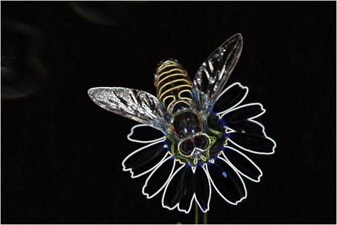
Bee Filter 3×3 Factor 5

Bee Filter 3x3 Factor 5

Sample Images

This article features several sample images provided as examples. All sample images were created using the sample application. All of the original source images used in generating sample images have been licensed by their respective authors to allow for reproduction here. The following section lists each original source image and related license and copyright details.

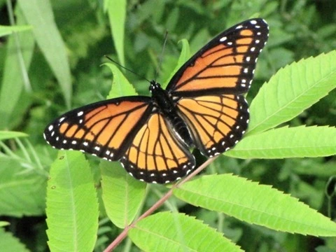
Viceroy (Limenitis archippus), Mer Bleue Conservation Area, Ottawa, Ontario © 2008 D. Gordon E. Robertson is used here under a Creative Commons Attribution-Share Alike 3.0 Unported license.

Viceroy (Limenitis archippus), Mer Bleue Conservation Area, Ottawa, Ontario


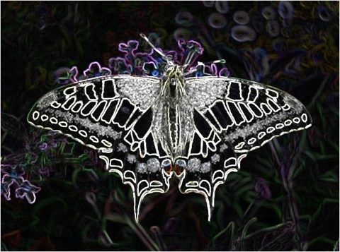
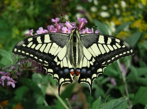
Old World Swallowtail on Buddleja davidii © 2008 Thomas Bresson is used here under a Creative Commons Attribution 2.0 Generic license.Old World Swallowtail on Buddleja davidii


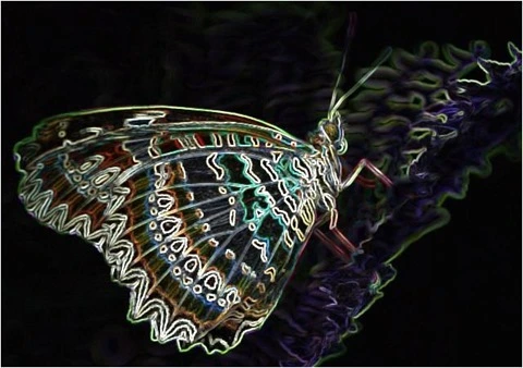
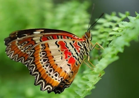
Cethosia cyane butterfly © 2006 Airbete is used here under a Creative Commons Attribution-Share Alike 3.0 Unported license.

Cethosia_cyane


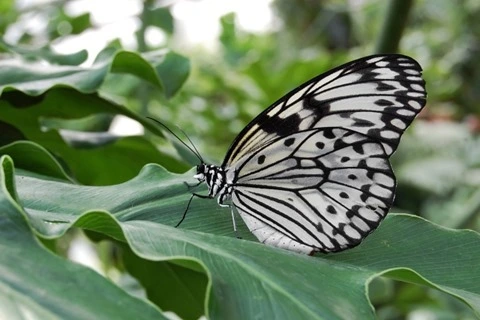
“Weiße Baumnymphe (Idea leuconoe) fotografiert im Schmetterlingshaus des Maximilianpark Hamm”  © 2009 Steffen Flor is used here under a  Creative Commons Attribution-Share Alike 3.0 Unported license.

Weiße Baumnymphe (Idea leuconoe) fotografiert im Schmetterlingshaus des Maximilianpark Hamm


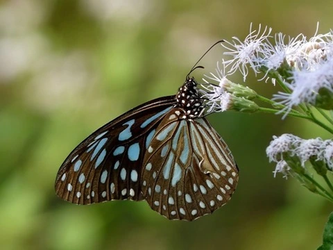
"Dark Blue Tiger tirumala septentrionis by kadavoor" © 2010 Jeevan Jose, Kerala, India is used here under a Creative Commons Attribution-ShareAlike 4.0 International License

Dark Blue Tiger tirumala septentrionis by kadavoor


"Common Lime Butterfly Papilio demoleus by Kadavoor" © 2010 Jeevan Jose, Kerala, India is used here under a Creative Commons Attribution-ShareAlike 4.0 International License

Common Lime Butterfly Papilio demoleus by Kadavoor


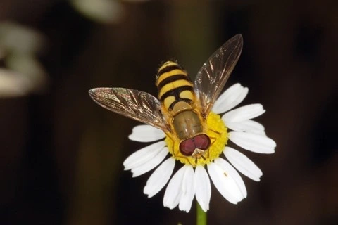
Syrphidae, Knüllwald, Hessen, Deutschland © 2007 Fritz Geller-Grimm is used here under a Creative Commons Attribution-Share Alike 3.0 Unported license

Syrphidae, Knüllwald, Hessen, Deutschland


Related Articles and Feedback

Feedback and questions are always encouraged. If you know of an alternative implementation or have ideas on a more efficient implementation please share in the comments section.

I’ve published a number of articles related to imaging and images of which you can find URL links here:

C# How to: Image Distortion Blur

Article Purpose

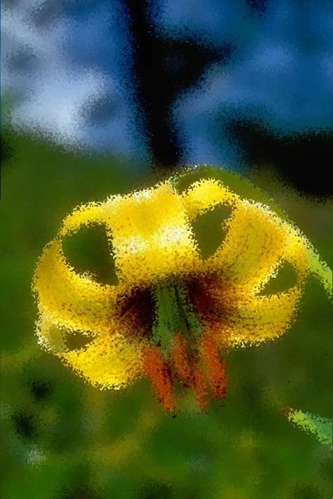
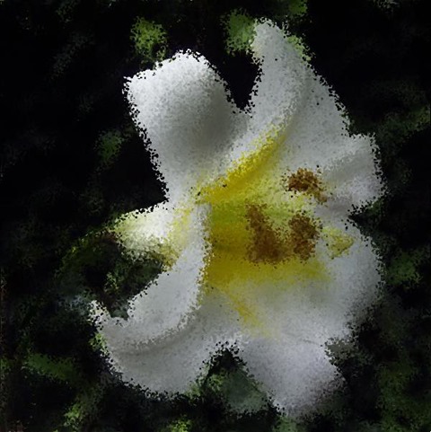
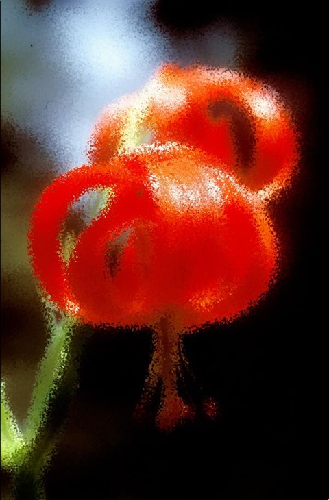
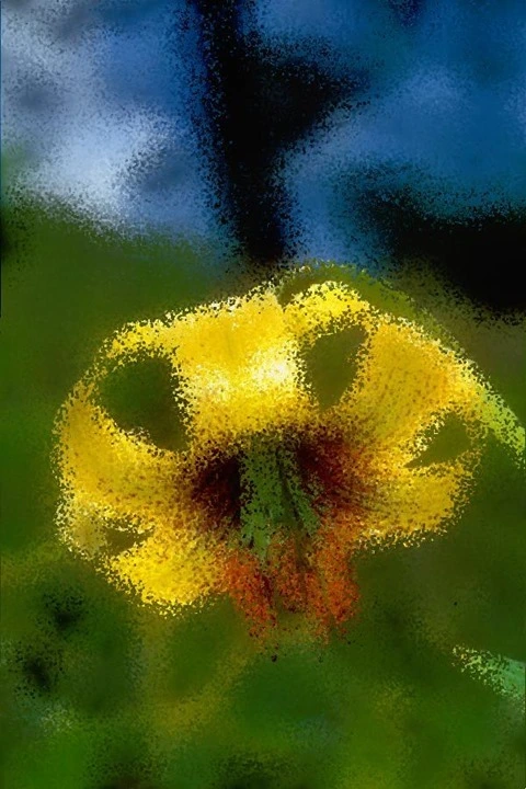
This article explores the process of implementing an Image Distortion Blur filter. This image filter is classified as a non-photo realistic image filter, primarily implemented in rendering artistic effects.

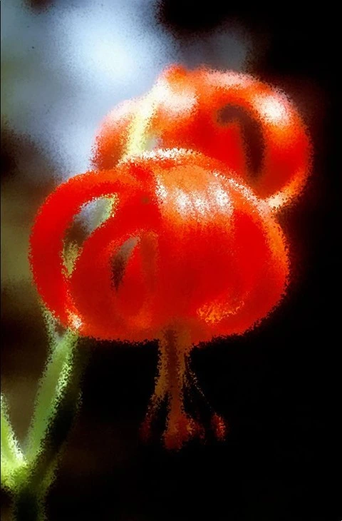
Flower: Distortion Factor 15

Flower: Distortion Factor 15

Sample Source Code

This article is accompanied by a sample source code Visual Studio project which is available for download here.

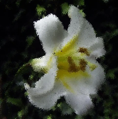
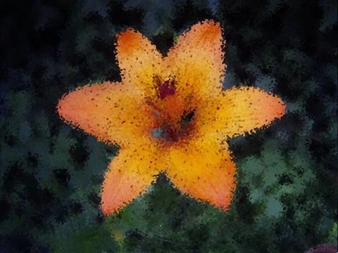
Flower: Distortion Factor 10

Flower: Distortion Factor 10

Using the Sample Application

The sample source code that accompanies this article includes a based sample application. The concepts explored in this article have all been implemented as part of the sample application. From an end user perspective the following configurable options are available:

  • Load/Save Images – Clicking the Load Image button allows a user to specify a source/input . If desired, output filtered can be saved to the local system by clicking the Save Image button.
  • Distortion Factor – The level or intensity of distortion applied when implementing the filter can be specified when adjusting the Distortion Factor through the user interface. Lower factor values result in less distortion being evident in resulting . Specifying higher factor values result in more intense distortion being applied.

The following image is screenshot of the Image Distortion Blur sample application:

ImageDistortionBlur_SampleApplication

Flower: Distortion Factor 10

Flower: Distortion Factor 10

Flower: Distortion Factor 10

Flower: Distortion Factor 10

Image Distortion

In this article and the accompanying sample source code are distorted through slightly adjusting each individual ’s coordinates. The direction and distance by which coordinates are adjusted differ per as a result of being randomly selected. The maximum distance offset applied depends on the user specified Distortion Factor. Once all coordinates have been updated, implementing a provides smoothing and an effect.

Applying an Image Distortion Filter requires implementing the following steps:

  1. Iterate Pixels – Each forming part of the source/input should be iterated.
  2. Calculate new Coordinates – For every being iterated generate two random values representing XY-coordinate offsets to be applied to a ’s current coordinates. Offset values can equate to less than zero in order to represent coordinates above or to the left of the current .
  3. Apply Median Filter – The newly offset will appear somewhat speckled in the resulting . Applying a reduces the speckled appearance whilst retaining a distortion effect.

Flower: Distortion Factor 10

Flower: Distortion Factor 10

Flower: Distortion Factor 10

Flower: Distortion Factor 10

Median Filter

Applying a is the final step required when implementing an Image Distortion Blur filter. are often implemented in reducing . The method of image distortion illustrated in this article express similarities when compared to . In order to soften the appearance of we implement a .

A can be applied through implementing the following steps:

  1. Iterate Pixels – Each forming part of the source/input should be iterated.
  2. Inspect Pixel Neighbourhood – Each neighbouring in relation to the currently being iterated should be added to a temporary collection.
  3. Determine Neighbourhood Median – Once all neighbourhood have been added to a temporary collection, sort the collection by value. The element value located at the middle of the collection represents the neighbourhood’s value.

Flower: Distortion Factor 10

Flower: Distortion Factor 10

Flower: Distortion Factor 15

Flower: Distortion Factor 15

Implementing Image Distortion

The sample source code defines the DistortionBlurFilter method, an targeting the class. The following code snippet illustrates the implementation:

public static Bitmap DistortionBlurFilter( 
         this Bitmap sourceBitmap, int distortFactor) 
{
    byte[] pixelBuffer = sourceBitmap.GetByteArray(); 
    byte[] resultBuffer = sourceBitmap.GetByteArray(); 

int imageStride = sourceBitmap.Width * 4; int calcOffset = 0, filterY = 0, filterX = 0; int factorMax = (distortFactor + 1) * 2; Random rand = new Random();
for (int k = 0; k + 4 < pixelBuffer.Length; k += 4) { filterY = distortFactor - rand.Next(0, factorMax); filterX = distortFactor - rand.Next(0, factorMax);
if (filterX * 4 + (k % imageStride) < imageStride && filterX * 4 + (k % imageStride) > 0) { calcOffset = k + filterY * imageStride + 4 * filterX;
if (calcOffset >= 0 && calcOffset + 4 < resultBuffer.Length) { resultBuffer[calcOffset] = pixelBuffer[k]; resultBuffer[calcOffset + 1] = pixelBuffer[k + 1]; resultBuffer[calcOffset + 2] = pixelBuffer[k + 2]; } } }
return resultBuffer.GetImage(sourceBitmap.Width, sourceBitmap.Height).MedianFilter(3); }

Flower: Distortion Factor 15

Flower: Distortion Factor 15

Implementing a Median Filter

The MedianFilter targets the class. The implementation as follows:

public static Bitmap MedianFilter(this Bitmap sourceBitmap, 
                                  int matrixSize) 
{ 
    byte[] pixelBuffer = sourceBitmap.GetByteArray(); 
    byte[] resultBuffer = new byte[pixelBuffer.Length]; 
    byte[] middlePixel; 

int imageStride = sourceBitmap.Width * 4; int filterOffset = (matrixSize - 1) / 2; int calcOffset = 0, filterY = 0, filterX = 0; List<int> neighbourPixels = new List<int>();
for (int k = 0; k + 4 < pixelBuffer.Length; k += 4) { filterY = -filterOffset; filterX = -filterOffset; neighbourPixels.Clear();
while (filterY <= filterOffset) { calcOffset = k + (filterX * 4) + (filterY * imageStride);
if (calcOffset > 0 && calcOffset + 4 < pixelBuffer.Length) { neighbourPixels.Add(BitConverter.ToInt32( pixelBuffer, calcOffset)); }
filterX++;
if (filterX > filterOffset) { filterX = -filterOffset; filterY++; } }
neighbourPixels.Sort(); middlePixel = BitConverter.GetBytes( neighbourPixels[filterOffset]);
resultBuffer[k] = middlePixel[0]; resultBuffer[k + 1] = middlePixel[1]; resultBuffer[k + 2] = middlePixel[2]; resultBuffer[k + 3] = middlePixel[3]; }
return resultBuffer.GetImage(sourceBitmap.Width, sourceBitmap.Height); }

Flower: Distortion Factor 25

Flower: Distortion Factor 25

Sample Images

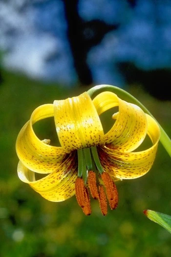
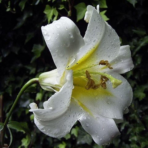
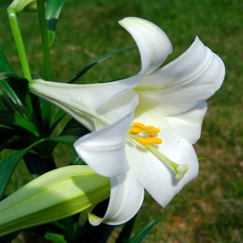
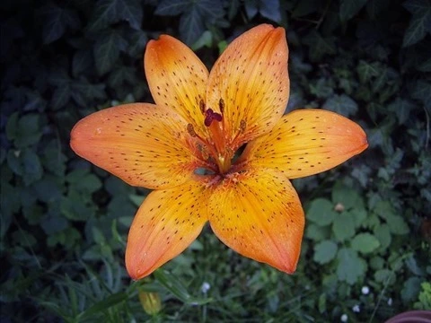
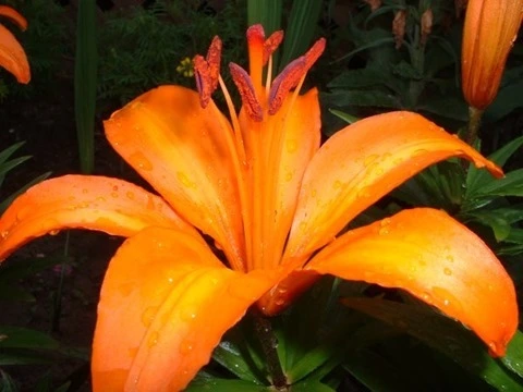
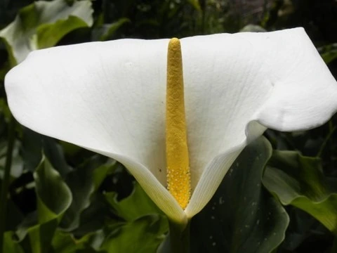
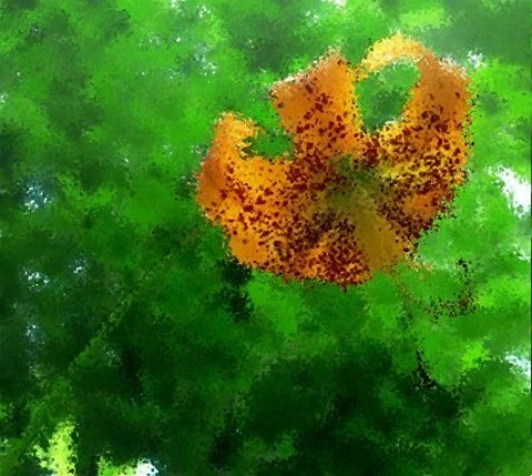
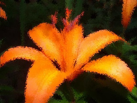
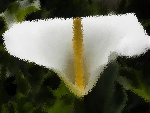
This article features a number of sample images. All featured images have been licensed allowing for reproduction. The following images feature as sample images:

674px-Lil_chalcedonicum_01EB_Griechenland_Hrisomiglia_17_07_01

683px-Lil_carniolicum_subsp_ponticum_01EB_Tuerkei_Ikizdere_02_07_93

1022px-LiliumSargentiae

1024px-Lilium_longiflorum_(Easter_Lily)

1280px-LiliumBulbiferumCroceumBologna

LiliumSuperbum1

Orange_Lilium_-_Relic38_-_Ontario_Canada

White_and_yellow_flower

Related Articles and Feedback

Feedback and questions are always encouraged. If you know of an alternative implementation or have ideas on a more efficient implementation please share in the comments section.

I’ve published a number of articles related to imaging and images of which you can find URL links here:

C# How to: Fuzzy Blur Filter
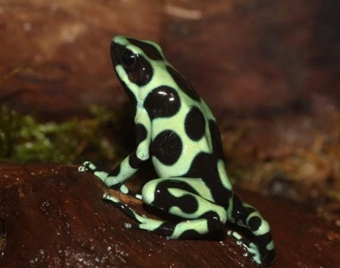
Article Purpose

This article serves to illustrate the concepts involved in implementing a Fuzzy Blur Filter. This filter results in rendering  non-photo realistic images which express a certain artistic effect.

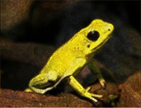
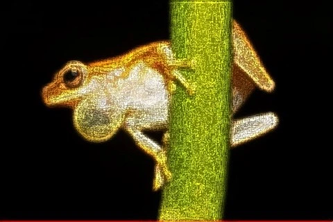
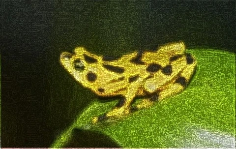
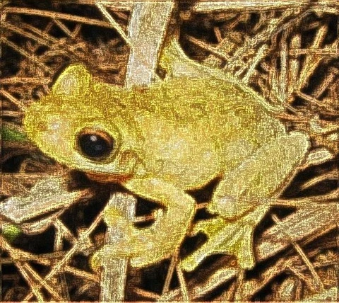
Frog: Filter Size 19×19

Frog: Filter Size 19x19

Sample Source Code

This article is accompanied by a sample source code Visual Studio project which is available for download here.

Using the Sample Application

The sample source code accompanying this article includes a based test application. The concepts explored throughout this article can be replicated/tested using the sample application.

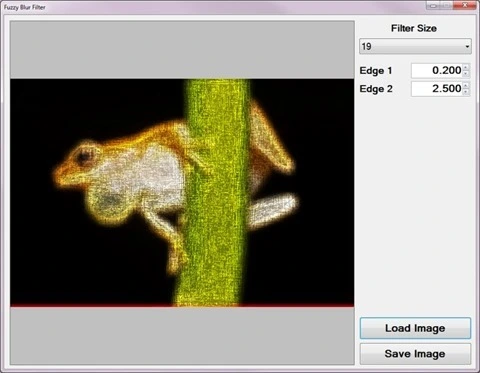
When executing the sample application the user interface exposes a number of configurable options:

  • Loading and Saving Images – Users are able to load source/input from the local system by clicking the Load Image button. Clicking the Save Image button allow users to save filter result .
  • Filter Size – The specified filter size affects the filter intensity. Smaller filter sizes result in less blurry being rendered, whereas larger filter sizes result in more blurry being rendered.
  • Edge Factors – The contrast of fuzzy expressed in resulting depend on the specified edge factor values. Values less than one result in detected being darkened and values greater than one result in detected image edges being lightened.

The following image is a screenshot of the Fuzzy Blur Filter sample application in action:

Fuzzy Blur Filter Sample Application
Frog: Filter Size 9×9

Frog: Filter Size 9x9

Fuzzy Blur Overview

The Fuzzy Blur Filter relies on the interference of when performing in order to create a fuzzy effect. In addition results from performing a .
The steps involved in performing a Fuzzy Blur Filter can be described as follows:
  1. Edge Detection and Enhancement – Using the first edge factor specified enhance by performing Boolean Edge detection. Being sensitive to , a fair amount of detected will actually be in addition to actual .
  2. Mean Filter Blur – Using the edge enhanced created in the previous step perform a blur. The enhanced edges will be blurred since a does not have edge preservation properties. The size of the implemented depends on a user specified value.
  3. Edge Detection and Enhancement –  Using the blurred created in the previous step once again perform Boolean Edge detection, enhancing detected edges according to the second edge factor specified.

Frog: Filter Size 9×9

Frog: Filter Size 9x9

Mean Filter

A Blur, also known as a , can be performed through . The size of the / implemented when preforming will be determined through user input.

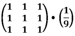
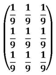
Every / element should be set to one. The resulting value should be multiplied by a factor value equating to one divided by the / size. As an example, a / size of 3×3 can be expressed as follows:

Mean Kernel

An alternative expression can also be:

Mean Kernel

Frog: Filter Size 9×9

Frog: Filter Size 9x9

Boolean Edge Detection without a local threshold

When performing Boolean Edge Detection a local threshold should be implemented in order to exclude . In this article we rely on the interference of in order to render a fuzzy effect. By not implementing a local threshold when performing Boolean Edge detection the sample source code ensures sufficient interference from .

The steps involved in performing Boolean Edge Detection without a local threshold can be described as follows:

  1. Calculate Neighbourhood Mean – Iterate each forming part of the source/input . Using a 3×3 size calculate the mean value of the neighbourhood surrounding the currently being iterated.
  2. Create Mean comparison Matrix – Once again using a 3×3 size compare each neighbourhood to the newly calculated mean value. Create a temporary 3×3 size , each element’s value should be the result of mean comparison. Should the value expressed by a neighbourhood exceed the mean value the corresponding temporary element should be set to one. When the calculated mean value exceeds the value of a neighbourhood the corresponding temporary  element should be set to zero.
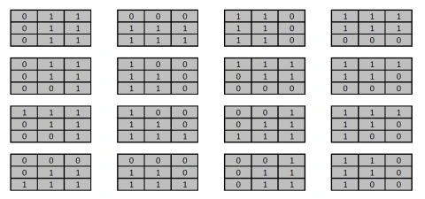
  3. Compare Edge Masks – Using sixteen predefined edge masks compare the temporary created in the previous step to each edge mask. If the temporary matches one of the predefined edge masks multiply the specified factor to the currently being iterated.

Note: A detailed article on Boolean Edge detection implementing a local threshold can be found here:

Frog: Filter Size 9×9

Frog: Filter Size 9x9

The sixteen predefined edge masks each represent an in a different direction. The predefined edge masks can be expressed as:

Boolean Edge Masks

Frog: Filter Size 13×13

Frog: Filter Size 13x13

Implementing a Mean Filter

The sample source code defines the MeanFilter method, an targeting the class. The definition listed as follows:

private static Bitmap MeanFilter(this Bitmap sourceBitmap, 
                                 int meanSize)
{
    byte[] pixelBuffer = sourceBitmap.GetByteArray(); 
    byte[] resultBuffer = new byte[pixelBuffer.Length];

double blue = 0.0, green = 0.0, red = 0.0; double factor = 1.0 / (meanSize * meanSize);
int imageStride = sourceBitmap.Width * 4; int filterOffset = meanSize / 2; int calcOffset = 0, filterY = 0, filterX = 0;
for (int k = 0; k + 4 < pixelBuffer.Length; k += 4) { blue = 0; green = 0; red = 0; filterY = -filterOffset; filterX = -filterOffset;
while (filterY <= filterOffset) { calcOffset = k + (filterX * 4) + (filterY * imageStride);
calcOffset = (calcOffset < 0 ? 0 : (calcOffset >= pixelBuffer.Length - 2 ? pixelBuffer.Length - 3 : calcOffset));
blue += pixelBuffer[calcOffset]; green += pixelBuffer[calcOffset + 1]; red += pixelBuffer[calcOffset + 2];
filterX++;
if (filterX > filterOffset) { filterX = -filterOffset; filterY++; } }
resultBuffer[k] = ClipByte(factor * blue); resultBuffer[k + 1] = ClipByte(factor * green); resultBuffer[k + 2] = ClipByte(factor * red); resultBuffer[k + 3] = 255; }
return resultBuffer.GetImage(sourceBitmap.Width, sourceBitmap.Height); }

Frog: Filter Size 19×19

Frog: Filter Size 19x19

Implementing Boolean Edge Detection

Boolean Edge detection is performed in the sample source code through the implementation of the BooleanEdgeDetectionFilter method. This method has been defined as an targeting the class.

The following code snippet provides the definition of the BooleanEdgeDetectionFilter :

public static Bitmap BooleanEdgeDetectionFilter( 
       this Bitmap sourceBitmap, float edgeFactor) 
{
    byte[] pixelBuffer = sourceBitmap.GetByteArray(); 
    byte[] resultBuffer = new byte[pixelBuffer.Length]; 
    Buffer.BlockCopy(pixelBuffer, 0, resultBuffer, 
                     0, pixelBuffer.Length); 

List<string> edgeMasks = GetBooleanEdgeMasks(); int imageStride = sourceBitmap.Width * 4; int matrixMean = 0, pixelTotal = 0; int filterY = 0, filterX = 0, calcOffset = 0; string matrixPatern = String.Empty;
for (int k = 0; k + 4 < pixelBuffer.Length; k += 4) { matrixPatern = String.Empty; matrixMean = 0; pixelTotal = 0; filterY = -1; filterX = -1;
while (filterY < 2) { calcOffset = k + (filterX * 4) + (filterY * imageStride);
calcOffset = (calcOffset < 0 ? 0 : (calcOffset >= pixelBuffer.Length - 2 ? pixelBuffer.Length - 3 : calcOffset)); matrixMean += pixelBuffer[calcOffset]; matrixMean += pixelBuffer[calcOffset + 1]; matrixMean += pixelBuffer[calcOffset + 2];
filterX += 1;
if (filterX > 1) { filterX = -1; filterY += 1; } }
matrixMean = matrixMean / 9; filterY = -1; filterX = -1;
while (filterY < 2) { calcOffset = k + (filterX * 4) + (filterY * imageStride);
calcOffset = (calcOffset < 0 ? 0 : (calcOffset >= pixelBuffer.Length - 2 ? pixelBuffer.Length - 3 : calcOffset));
pixelTotal = pixelBuffer[calcOffset]; pixelTotal += pixelBuffer[calcOffset + 1]; pixelTotal += pixelBuffer[calcOffset + 2]; matrixPatern += (pixelTotal > matrixMean ? "1" : "0"); filterX += 1;
if (filterX > 1) { filterX = -1; filterY += 1; } }
if (edgeMasks.Contains(matrixPatern)) { resultBuffer[k] = ClipByte(resultBuffer[k] * edgeFactor);
resultBuffer[k + 1] = ClipByte(resultBuffer[k + 1] * edgeFactor);
resultBuffer[k + 2] = ClipByte(resultBuffer[k + 2] * edgeFactor); } }
return resultBuffer.GetImage(sourceBitmap.Width, sourceBitmap.Height); }

Frog: Filter Size 13×13

Frog: Filter Size 13x13

The predefined edge masks implemented in mean comparison have been wrapped by the GetBooleanEdgeMasks method. The definition as follows:

public static List<string> GetBooleanEdgeMasks() 
{
    List<string> edgeMasks = new List<string>(); 

edgeMasks.Add("011011011"); edgeMasks.Add("000111111"); edgeMasks.Add("110110110"); edgeMasks.Add("111111000"); edgeMasks.Add("011011001"); edgeMasks.Add("100110110"); edgeMasks.Add("111011000"); edgeMasks.Add("111110000"); edgeMasks.Add("111011001"); edgeMasks.Add("100110111"); edgeMasks.Add("001011111"); edgeMasks.Add("111110100"); edgeMasks.Add("000011111"); edgeMasks.Add("000110111"); edgeMasks.Add("001011011"); edgeMasks.Add("110110100");
return edgeMasks; }

Frog: Filter Size 19×19

Frog: Filter Size 19x19

Implementing a Fuzzy Blur Filter
The FuzzyEdgeBlurFilter method serves as the implementation of a Fuzzy Blur Filter. As discussed earlier a Fuzzy Blur Filter involves enhancing through Boolean Edge detection, performing a blur and then once again performing Boolean Edge detection. This method has been defined as an extension method targeting the class.
The following code snippet provides the definition of the FuzzyEdgeBlurFilter method:

public static Bitmap FuzzyEdgeBlurFilter(this Bitmap sourceBitmap,  
                                         int filterSize,  
                                         float edgeFactor1,  
                                         float edgeFactor2) 
{
    return  
    sourceBitmap.BooleanEdgeDetectionFilter(edgeFactor1). 
    MeanFilter(filterSize).BooleanEdgeDetectionFilter(edgeFactor2); 
}

Frog: Filter Size 3×3
Frog: Filter Size 3x3

Sample Images

This article features a number of sample images. All featured images have been licensed allowing for reproduction. The following images feature as sample images:

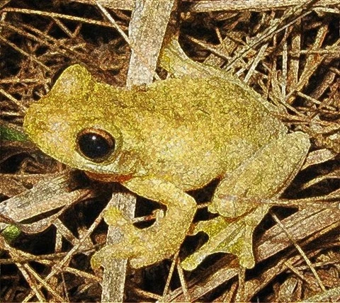
Litoria_tyleri

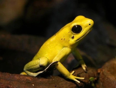
Schrecklicherpfeilgiftfrosch-01

Dendropsophus_microcephalus_-_calling_male_(Cope,_1886)

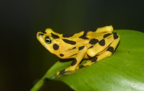
Atelopus_zeteki1

Related Articles and Feedback

Feedback and questions are always encouraged. If you know of an alternative implementation or have ideas on a more efficient implementation please share in the comments section.

I’ve published a number of articles related to imaging and images of which you can find URL links here:

C# How to: Image Boundary Extraction

Article Purpose

This article explores various concepts, which feature in combination when implementing Image Boundary Extraction. Concepts covered within this article include: Morphological and , Addition and Subtraction, Boundary Sharpening, Boundary Tracing and Boundary Extraction.

Parrot: Boundary Extraction, 3×3, Red, Green, Blue

Parrot: Boundary Extraction, 3x3, Red, Greed, Blue

Sample Source Code

This article is accompanied by a sample source code Visual Studio project which is available for download .

Using the Sample Application

This article’s accompanying sample source code includes the definition of a sample application. The sample application serves as an implementation of the concepts discussed in this article. In using the sample application concepts can be easily tested and replicated.

The sample application has been defined as a . The user interface enables the user to configure several options which influence the output produced from filtering processes. The following section describes the options available to a user when executing the sample application:

  • Loading and Saving files – Users can specify source/input through clicking the Load Image button. If desired, resulting filtered can be saved to the local system when clicking the Save Image button.
  • Filter Type – The types of filters implemented represent variations on Image Boundary Extraction. The supported filter types are: Conventional Boundary extraction, Boundary Sharpening and Boundary Tracing.
  • Filter Size – Filter intensity/strength will mostly be reliant on the filter size implemented. A Filter size represents the number of neighbouring examined when applying filters.
  • Colours Applied – The sample source code and sample application provides functionality allowing a filter to only effect user specified colour components. Colour components are represented in the form of an RGB colour scheme. The inclusion or exclusion of the colour components Red, Green and Blue will be determined through user configuration.
  • Structuring Element – As mentioned, the Filter Size option determines the size of neighbourhood examined. The ’s setup determine the neighbouring   within the neighbourhood size bounds that should be used as input when calculating filter results.

The following is a screenshot of the Image Boundary Extraction sample application in action:

Image Boundary Extaction Sample  Application

Parrot: Boundary Extraction, 3×3, Green

Parrot: Boundary Extraction, 3x3, Green

Morphological Boundary Extraction

Image Boundary Extraction can be considered a method of . In contrast to more commonly implemented   methods, Image Boundary Extraction originates from Morphological Image Filters.

When drawing a comparison, Image Boundary Extraction and express strong similarities. results from the difference in and . Considered from a different point of view, creating one expressing thicker edges and another expressing thinner edges provides the means to calculate the difference in edges.

Image Boundary Extraction implements the same concept as . The base concept can be regarded as calculating the difference between two which rendered the same , but expressing a difference in . Image Boundary Extraction relies on calculating the difference between either and the source or and the source . The difference between and in most cases result in more of difference than the difference between and the source or and the source . The result of Image Boundary Extraction representing less of a difference than can be observed in Image Boundary Extraction being expressed in finer/smaller width lines.

is another method of which functions along the same basis. Edges are determined by calculating the difference between two , each having been filtered from the same source , using a of differing intensity levels.

Parrot: Boundary Extraction, 3×3, Red, Green, Blue

Parrot: Boundary Extraction, 3x3, Red, Green, Blue

Boundary Sharpening

The concept of Boundary Sharpening refers to enhancing or sharpening the boundaries or edges expressed in a source/input . Boundaries can be easily determined or extracted as discussed earlier when exploring Boundary Extraction.

The steps involved in performing Boundary Sharpening can be described as follows:

  1. Extract Boundaries – Determine boundaries by performing and calculating the difference between the dilated and the source .
  2. Match Source Edges and Extracted Boundaries – The boundaries extracted in the previous step represent the difference between and the original source . Ensure that extracted boundaries match the source through performing on a copy of the source/input .
  3. Emphasise Extracted boundaries in source image – Perform addition using the extracted boundaries and dilated copy of the source .

Parrot: Boundary Extraction, 3×3, Red, Green, Blue

Parrot: Boundary Extraction, 3x3, Red, Green, Blue

Boundary Tracing

Boundary Tracing refers to applying filters which result in /boundaries appearing darker or more pronounced. This type of filter also relies on Boundary Extraction.

Boundary Tracing can be implemented in two steps, described as follows:

  1. Extract Boundaries – Determine boundaries by performing and calculating the difference between the dilated and the source .
  2. Emphasise Extracted boundaries in source image – Subtract the extracted boundaries from the original source .

Parrot: Boundary Extraction, 3×3, Red, Green, Blue

Parrot: Boundary Extraction, 3x3, Red, Green, Blue

Implementing Morphological Erosion and Dilation

The accompanying sample source code defines the MorphologyOperation method,  defined as an targeting the class. In terms of parameters this method expects a two dimensional array representing a . The other required  parameter represents an value indicating which Morphological Operation to perform, either or .

The following code snippet provides the definition in full:

private static Bitmap MorphologyOperation(this Bitmap sourceBitmap,
                                          bool[,] se,
                                          MorphologyOperationType morphType,
                                          bool applyBlue = true,
                                          bool applyGreen = true,
                                          bool applyRed = true)
{ 
    BitmapData sourceData =
               sourceBitmap.LockBits(new Rectangle(0, 0,
               sourceBitmap.Width, sourceBitmap.Height),
               ImageLockMode.ReadOnly,
               PixelFormat.Format32bppArgb);

byte[] pixelBuffer = new byte[sourceData.Stride * sourceData.Height];
byte[] resultBuffer = new byte[sourceData.Stride * sourceData.Height];
Marshal.Copy(sourceData.Scan0, pixelBuffer, 0, pixelBuffer.Length);
sourceBitmap.UnlockBits(sourceData);
int filterOffset = (se.GetLength(0) - 1) / 2; int calcOffset = 0, byteOffset = 0; byte blueErode = 0, greenErode = 0, redErode = 0; byte blueDilate = 0, greenDilate = 0, redDilate = 0;
for (int offsetY = 0; offsetY < sourceBitmap.Height - filterOffset; offsetY++) { for (int offsetX = 0; offsetX < sourceBitmap.Width - filterOffset; offsetX++) { byteOffset = offsetY * sourceData.Stride + offsetX * 4;
blueErode = 255; greenErode = 255; redErode = 255; blueDilate = 0; greenDilate = 0; redDilate = 0;
for (int filterY = -filterOffset; filterY <= filterOffset; filterY++) { for (int filterX = -filterOffset; filterX <= filterOffset; filterX++) { if (se[filterY + filterOffset, filterX + filterOffset] == true) { calcOffset = byteOffset + (filterX * 4) + (filterY * sourceData.Stride);
calcOffset = (calcOffset < 0 ? 0 : (calcOffset >= pixelBuffer.Length + 2 ? pixelBuffer.Length - 3 : calcOffset));
blueDilate = (pixelBuffer[calcOffset] > blueDilate ? pixelBuffer[calcOffset] : blueDilate);
greenDilate = (pixelBuffer[calcOffset + 1] > greenDilate ? pixelBuffer[calcOffset + 1] : greenDilate);
redDilate = (pixelBuffer[calcOffset + 2] > redDilate ? pixelBuffer[calcOffset + 2] : redDilate);
blueErode = (pixelBuffer[calcOffset] < blueErode ? pixelBuffer[calcOffset] : blueErode);
greenErode = (pixelBuffer[calcOffset + 1] < greenErode ? pixelBuffer[calcOffset + 1] : greenErode);
redErode = (pixelBuffer[calcOffset + 2] < redErode ? pixelBuffer[calcOffset + 2] : redErode); } } }
blueErode = (applyBlue ? blueErode : pixelBuffer[byteOffset]); blueDilate = (applyBlue ? blueDilate : pixelBuffer[byteOffset]);
greenErode = (applyGreen ? greenErode : pixelBuffer[byteOffset + 1]); greenDilate = (applyGreen ? greenDilate : pixelBuffer[byteOffset + 1]);
redErode = (applyRed ? redErode : pixelBuffer[byteOffset + 2]); redDilate = (applyRed ? redDilate : pixelBuffer[byteOffset + 2]);
if (morphType == MorphologyOperationType.Erosion) { resultBuffer[byteOffset] = blueErode; resultBuffer[byteOffset + 1] = greenErode; resultBuffer[byteOffset + 2] = redErode; } else if (morphType == MorphologyOperationType.Dilation) { resultBuffer[byteOffset] = blueDilate; resultBuffer[byteOffset + 1] = greenDilate; resultBuffer[byteOffset + 2] = redDilate; }
resultBuffer[byteOffset + 3] = 255; } }
Bitmap resultBitmap = new Bitmap(sourceBitmap.Width, sourceBitmap.Height); BitmapData resultData = resultBitmap.LockBits(new Rectangle(0, 0, resultBitmap.Width, resultBitmap.Height), ImageLockMode.WriteOnly, PixelFormat.Format32bppArgb);
Marshal.Copy(resultBuffer, 0, resultData.Scan0, resultBuffer.Length);
resultBitmap.UnlockBits(resultData);
return resultBitmap; }

Parrot: Boundary Extraction, 3×3, Red, Green

Parrot: Boundary Extraction, 3x3, Red, Green

Implementing Image Addition

The sample source code encapsulates the process of combining two separate through means of addition. The AddImage method serves as a single declaration of addition functionality. This method has been defined as an targeting the class. Boundary Sharpen filtering implements addition.

The following code snippet provides the definition of the AddImage :

private static Bitmap AddImage(this Bitmapsource Bitmap, 
                               Bitmap addBitmap)
{
    BitmapData sourceData =
               sourceBitmap.LockBits(new Rectangle (0, 0,
               sourceBitmap.Width, sourceBitmap.Height),
               ImageLockMode.ReadOnly,
               PixelFormat.Format32bppArgb);

byte[] resultBuffer = new byte[sourceData.Stride * sourceData.Height];
Marshal.Copy(sourceData.Scan0, resultBuffer, 0, resultBuffer.Length);
sourceBitmap.UnlockBits(sourceData);
BitmapData addData = addBitmap.LockBits(new Rectangle(0, 0, addBitmap.Width, addBitmap.Height), ImageLockMode.ReadOnly, PixelFormat.Format32bppArgb);
byte[] addBuffer = new byte[addData.Stride * addData.Height];
Marshal.Copy(addData.Scan0, addBuffer, 0, addBuffer.Length);
addBitmap.UnlockBits(addData);
for (int k = 0; k + 4 < resultBuffer.Length && k + 4 < addBuffer.Length; k += 4) { resultBuffer[k] = AddColors(resultBuffer[k], addBuffer[k]); resultBuffer[k + 1] = AddColors(resultBuffer[k + 1], addBuffer[k + 1]); resultBuffer[k + 2] = AddColors(resultBuffer[k + 2], addBuffer[k + 2]); resultBuffer[k + 3] = 255; }
Bitmap resultBitmap = new Bitmap(sourceBitmap.Width, sourceBitmap.Height);
BitmapData resultData = resultBitmap.LockBits(new Rectangle(0, 0, resultBitmap.Width, resultBitmap.Height), ImageLockMode.WriteOnly, PixelFormat.Format32bppArgb);
Marshal.Copy(resultBuffer, 0, resultData.Scan0, resultBuffer.Length);
resultBitmap.UnlockBits(resultData);
return resultBitmap; }
private static byte AddColors(byte color1, byte color2) 
{
    int result = color1 + color2; 

return (byte)(result < 0 ? 0 : (result > 255 ? 255 : result)); }

Parrot: Boundary Extraction, 3×3, Red, Green, Blue

Parrot: Boundary Extraction, 3x3, Red, Green, Blue

Implementing Image Subtraction

In a similar fashion regarding the AddImage method the sample code defines the SubractImage method.  By definition this method serves as an targeting the class. Image subtraction has been implemented in Boundary Extraction and Boundary Tracing.

The definition of the SubtractImage method listed as follows:

private static Bitmap SubtractImage(this Bitmap sourceBitmap,  
                                         Bitmap subtractBitmap) 
{
    BitmapData sourceData = 
               sourceBitmap.LockBits(new Rectangle(0, 0, 
               sourceBitmap.Width, sourceBitmap.Height), 
               ImageLockMode.ReadOnly, 
               PixelFormat.Format32bppArgb); 

byte[] resultBuffer = new byte[sourceData.Stride * sourceData.Height];
Marshal.Copy(sourceData.Scan0, resultBuffer, 0, resultBuffer.Length);
sourceBitmap.UnlockBits(sourceData);
BitmapData subtractData = subtractBitmap.LockBits(new Rectangle(0, 0, subtractBitmap.Width, subtractBitmap.Height), ImageLockMode.ReadOnly, PixelFormat.Format32bppArgb);
byte[] subtractBuffer = new byte[subtractData.Stride * subtractData.Height];
Marshal.Copy(subtractData.Scan0, subtractBuffer, 0, subtractBuffer.Length);
subtractBitmap.UnlockBits(subtractData);
for (int k = 0; k + 4 < resultBuffer.Length && k + 4 < subtractBuffer.Length; k += 4) { resultBuffer[k] = SubtractColors(resultBuffer[k], subtractBuffer[k]);
resultBuffer[k + 1] = SubtractColors(resultBuffer[k + 1], subtractBuffer[k + 1]);
resultBuffer[k + 2] = SubtractColors(resultBuffer[k + 2], subtractBuffer[k + 2]);
resultBuffer[k + 3] = 255; }
Bitmap resultBitmap = new Bitmap (sourceBitmap.Width, sourceBitmap.Height);
BitmapData resultData = resultBitmap.LockBits(new Rectangle (0, 0, resultBitmap.Width, resultBitmap.Height), ImageLockMode.WriteOnly, PixelFormat.Format32bppArgb);
Marshal.Copy(resultBuffer, 0, resultData.Scan0, resultBuffer.Length);
resultBitmap.UnlockBits(resultData);
return resultBitmap; }
private static byte SubtractColors(byte color1, byte color2) 
{
    int result = (int)color1 - (int)color2; 

return (byte)(result < 0 ? 0 : result); }

 Parrot: Boundary Extraction, 3×3, Green

Parrot: Boundary Extraction, 3x3, Green

Implementing Image Boundary Extraction

In the sample source code processing Image Boundary Extraction can be achieved when invoking the BoundaryExtraction method. Defined as an , the BoundaryExtraction method targets the class.

As discussed earlier, this method performs Boundary Extraction through subtracting the source from a dilated copy of the source .

The following code snippet details the definition of the BoundaryExtraction method:

private static Bitmap
BoundaryExtraction(this Bitmap sourceBitmap, 
                   bool[,] se, bool applyBlue = true, 
                   bool applyGreen = true, bool applyRed = true) 
{
    Bitmap resultBitmap = 
           sourceBitmap.MorphologyOperation(se,  
           MorphologyOperationType.Dilation, applyBlue,  
                                  applyGreen, applyRed); 

resultBitmap = resultBitmap.SubtractImage(sourceBitmap);
return resultBitmap; }

Parrot: Boundary Extraction, 3×3, Red, Blue

Parrot: Boundary Extraction, 3x3, Red, Blue

Implementing Image Boundary Sharpening

Boundary Sharpening in the sample source code has been implemented through the definition of the BoundarySharpen method. The BoundarySharpen targets the class. The following code snippet provides the definition:

private static Bitmap 
BoundarySharpen(this Bitmap sourceBitmap, 
                bool[,] se, bool applyBlue = true, 
                bool applyGreen = true, bool applyRed = true) 
{
    Bitmap resultBitmap = 
           sourceBitmap.BoundaryExtraction(se, applyBlue, 
                                           applyGreen, applyRed); 

resultBitmap = sourceBitmap.MorphologyOperation(se, MorphologyOperationType.Dilation, applyBlue, applyGreen, applyRed).AddImage(resultBitmap);
return resultBitmap; }

Parrot: Boundary Extraction, 3×3, Green

Parrot: Boundary Extraction, 3x3, Green

Implementing Image Boundary Tracing

Boundary Tracing has been defined through the BoundaryTrace , which targets the class. Similar to the BoundarySharpen method this method performs Boundary Extraction, the result of which serves to be subtracted from the original source . Subtracting boundaries/edges result in those boundaries/edges being darkened, or traced. The definition of the BoundaryTracing detailed as follows:

private static Bitmap
BoundaryTrace(this Bitmap sourceBitmap, 
              bool[,] se, bool applyBlue = true, 
              bool applyGreen = true, bool applyRed = true) 
{
    Bitmap resultBitmap =
    sourceBitmap.BoundaryExtraction(se, applyBlue,  
                                    applyGreen, applyRed); 

resultBitmap = sourceBitmap.SubtractImage(resultBitmap);
return resultBitmap; }

Parrot: Boundary Extraction, 3×3, Green, Blue

Parrot: Boundary Extraction, 3x3, Green, Blue

Implementing a Wrapper Method

The BoundaryExtractionFilter method is the only method defined as publicly accessible. Following convention, this method’s definition signals the method as an targeting the class. This method has the intention of acting as a wrapper method, a single method capable of performing Boundary Extraction, Boundary Sharpening and Boundary Tracing, depending on method parameters.

The definition of the BoundaryExtractionFilter method detailed by the following code snippet:

public static Bitmap
BoundaryExtractionFilter(this Bitmap sourceBitmap, 
                         bool[,] se, BoundaryExtractionFilterType  
                         filterType, bool applyBlue = true, 
                         bool applyGreen = true, bool applyRed = true) 
{
    Bitmap resultBitmap = null; 

if (filterType == BoundaryExtractionFilterType.BoundaryExtraction) { resultBitmap = sourceBitmap.BoundaryExtraction(se, applyBlue, applyGreen, applyRed); } else if (filterType == BoundaryExtractionFilterType.BoundarySharpen) { resultBitmap = sourceBitmap.BoundarySharpen(se, applyBlue, applyGreen, applyRed); } else if (filterType == BoundaryExtractionFilterType.BoundaryTrace) { resultBitmap = sourceBitmap.BoundaryTrace(se, applyBlue, applyGreen, applyRed); }
return resultBitmap; }

Parrot: Boundary Extraction, 3×3, Red, Green, Blue

Parrot: Boundary Extraction, 3x3, Red, Green, Blue

Sample Images

This article features a number of sample images. All featured images have been licensed allowing for reproduction. The following images feature as sample images:

1280px-Ara_macao_-Diergaarde_Blijdorp_-flying-8a

Ara_macao_-flying_away-8a

Ara_ararauna_Luc_Viatour

1280px-Macaws_at_Seaport_Village_-USA-8a

Ara_macao_-on_a_small_bicycle-8

Psarisomus_dalhousiae_-_Kaeng_Krachan

Related Articles and Feedback

Feedback and questions are always encouraged. If you know of an alternative implementation or have ideas on a more efficient implementation please share in the comments section.

I’ve published a number of articles related to imaging and images of which you can find URL links here:


Dewald Esterhuizen

Blog Stats

  • 869,813 hits

Enter your email address to follow and receive notifications of new posts by email.

Join 228 other subscribers

Archives

RSS SoftwareByDefault on MSDN

  • An error has occurred; the feed is probably down. Try again later.