Article purpose
In this article we explore how to combine or blend two Bitmap images by implementing various colour filters affecting how an Image appear as part of the resulting blended image. The concepts detailed in this article are reinforced and easily reproduced by making use of the sample source code that accompanies this article.
Sample source code
This article is accompanied by a sample source code Visual Studio project which is available for download here.

Using the sample Application
The provided sample source code builds a Windows Forms application which can be used to blend two separate image files read from the file system. The methods employed when applying blending operations on two bitmaps can be adjusted to a fine degree when using the sample application. In addition the sample application provides the functionality allowing the user to save the resulting blended image and also being able to save the exact colour filters/algorithms that were applied. Filters created and saved previously can be loaded from the file system allowing users to apply the exact same filtering without having to reconfigure filtering as exposed through the application front end.
Here is a screenshot of the sample application in action:

This scenario blends an image of an airplane with an image of a pathway in a forest. As a result of the colour filtering implemented when blending the two images the output image appears to provide somewhat equal elements of both images, without expressing all the elements of the original images.
What is Colour Filtering?
In general terms making reference to a filter would imply some or other mechanism being capable of sorting or providing selective inclusion/exclusion. There is a vast number of filter algorithms in existence, each applying some form of logic in order to achieve a desired outcome.
In C# implementing colour filter algorithms targeting images have the ability to modify or manipulate the colour values expressed by an image. The extent to which colour values change as well as the level of detail implemented is determined by the algorithms/calculations performed when a filter operation becomes active.
An image can be thought of as being similar to a two dimensional array with each array element representing the data required to be expressed as an individual pixel. Two dimensional arrays are similar to the concept of a grid defined by rows and columns. The “rows” of pixels represented by an image are required to all be of equal length. When thinking in terms of a two dimensional array or grid analogy its likely to make sense that the number of rows and columns in fact translate to an image’s width and height.
An image’s colour data can be expressed beyond rows and columns of pixels. Each pixel contained in an image defines a colour value. In this article we focus on 32bit images of type ARGB.
Image Bit Depth and Pixel Colour components
Image bit depth is also referred to as the number of bits per pixel. Bits per pixel (Bpp) is an indicator of the amount of storage space required to store an image. A bit value is smallest unit of storage available in a storage medium, it can simply be referred to as being either a value of 1 or 0.
In C# natively the smallest unit of storage expressed comes in the form of the byte integral type. A byte value occupies 8 bits of storage, it is not possible in C# to express a value as a bit. The .net framework provides functionality enabling developers to develop in the concept of bit values, which in reality occupies far more than 1 bit of memory when implemented.
If we consider as an example an image formatted as 32 bits per pixel, as the name implies, for each pixel contained in an image 32 bits of additional storage is required. Knowing that a byte represents 8 bits logic dictates that 32 bits are equal to four bytes, determined by dividing 32 bits by 8. Images format as 32 bits per pixel therefore can be considered as being encoded as 4 bytes per pixel images. 32 Bpp images require 4 bytes to express a single pixel.
The data represented by a pixel’s bytes
32 Bpp equating to 4 bytes per pixel, each byte in turn representing a colour component, together being capable of expressing a single colour representing the underlying pixel. When an image format is referred to as 32 Bpp Argb the four colour components contained in each pixel are: Red, Green, Blue and the Alpha component.
An Alpha component is in indication of a particular pixel’s transparency. Each colour component is represented by a byte value. The possible value range in terms of bytes stretch from 0 to 255, inclusive, therefore a colour component can only contain a value within this range. A colour value is in fact a representation of that colour’s intensity associated with a single image pixel. A value of 0 indicating the highest possible intensity and 255 reflecting no intensity at all. When the Alpha component is set to a value of 255 it is an expression of no transparency. In the same fashion when an Alpha component equates to 0 the associated pixel is considered completely transparent, thus negating whatever colour values are expressed by the remaining colour components.
Take note that not all image formats support transparency, almost similar to how certain Image formats can only represent grayscale or just black and white pixels. An image expressed only in terms of Red, Blue and Green colour values, containing no Alpha component can be implemented as a 24 Bit RGB image format. Each pixel’s storage requirement being 24 bits or 3 bytes, representing colour intensity values for Red, Green and Blue, each limited to a value ranging from 0 to 255.
Manipulating a Pixel’s individual colour components
In C# it is possible to manipulate the value of a pixel’s individual colour components. Updating the value expressed by a colour component will most likely result in the colour value expressed by the pixel as a whole to also change. The resulting change affects the colour component’s intensity. As an example, if you were to double the value of the Blue colour component the result will most likely be that the associated pixel will represent a colour having twice the intensity of Blue when compared to the previous value.
When you manipulate colour components you are in affect applying a colour filter to the underlying image. Iterating the byte values and performing updates based on a calculation or a conditional check qualifies as an algorithm, an image/colour filter in other words.
Retrieving Image Colour components as an array of bytes
As a result of the .net Framework’s memory handling infrastructure and the implementation of the Garbage Collector it is a likely possibility that the memory address assigned to a variable when instantiated could change during the variable’s lifetime and scope, not necessarily reflecting the same address in memory when going out of scope. It is the responsibility of the Garbage Collector to ensure updating a variable’s memory reference when an operation performed by the Garbage Collector results in values kept in memory moving to a new address in memory.
When accessing an Image’s underlying data expressed as a byte array we require a mechanism to signal the Garbage Collector that an additional memory reference exist, which might not be updated when values shift in memory to a new address.
The Bitmap class provides the LockBits method, when invoked the byte values representing pixel data will not be moved in memory by the Garbage Collector until the values are unlocked by invoking the Bitmap.UnlockBits method also defined by the Bitmap class.
The LockBits method defines a return value of type BitmapData, which contains data related to the lock operation. When invoking the Bitmap.UnlockBits method you are required to pass the BitmapData object returned when you invoked LockBits.
The LockBits method provides an overridden implementation allowing the calling code to specify only a certain part of a Bitmap to lock in memory, expressed as Rectangle Structure.
The sample code that accompanies this article updates the entire Bitmap and therefore specifies the Bitmap portion to lock as a Rectangle Structure equal in size to the whole Bitmap.
The BitmapData class defines the Scan0 property of type IntPtr. BitmapData.Scan0 contains the address in memory of the Bitmap’s first pixel, in other words the starting point of a Bitmap’s underlying data.
Creating an algorithm to Filter Bitmap Colour components
The sample code is implemented to blend two Bitmaps, considering one Bitmap as as source or base canvas and the second as an overlay Bitmap. The algorithm used to implement a blending operation is defined as a class exposing public properties which affect how image blending is achieved.
The source code that implements the algorithm functions by creating an object instance of BitmapFilterData class and setting the associated public properties to certain values, as specified by the user through the user interface at runtime. The BitmapFilterData class can thus be considered to qualify as a dynamic algorithm. The following source code contains the definition of the BitmapFilterData class.
[Serializable]
public class BitmapFilterData
{
    private bool sourceBlueEnabled = false;
    public bool SourceBlueEnabled { get { return sourceBlueEnabled; }set { sourceBlueEnabled = value; } }


    private bool sourceGreenEnabled = false;
    public bool SourceGreenEnabled { get { return sourceGreenEnabled; }set { sourceGreenEnabled = value; } }


    private bool sourceRedEnabled = false;
    public bool SourceRedEnabled { get { return sourceRedEnabled; } set { sourceRedEnabled = value; } }


    private bool overlayBlueEnabled = false;
    public bool OverlayBlueEnabled { get { return overlayBlueEnabled; } set { overlayBlueEnabled = value; } }


    private bool overlayGreenEnabled = false;
    public bool OverlayGreenEnabled { get { return overlayGreenEnabled; } set { overlayGreenEnabled = value; } }


    private bool overlayRedEnabled = false;
    public bool OverlayRedEnabled { get { return overlayRedEnabled; }set { overlayRedEnabled = value; } }


    private float sourceBlueLevel = 1.0f;
    public float SourceBlueLevel { get { return sourceBlueLevel; } set { sourceBlueLevel = value; } }


    private float sourceGreenLevel = 1.0f;
    public float SourceGreenLevel { get { return sourceGreenLevel; } set { sourceGreenLevel = value; } }


    private float sourceRedLevel = 1.0f;
    public float SourceRedLevel {get { return sourceRedLevel; } set { sourceRedLevel = value; } }


    private float overlayBlueLevel = 0.0f;
    public float OverlayBlueLevel { get { return overlayBlueLevel; } set { overlayBlueLevel = value; } }


    private float overlayGreenLevel = 0.0f;
    public float OverlayGreenLevel { get { return overlayGreenLevel; } set { overlayGreenLevel = value; } }


    private float overlayRedLevel = 0.0f;
    public float OverlayRedLevel { get { return overlayRedLevel; } set { overlayRedLevel = value; } }


    private ColorComponentBlendType blendTypeBlue = ColorComponentBlendType.Add;
    public ColorComponentBlendType BlendTypeBlue { get { return blendTypeBlue; }set { blendTypeBlue = value; } }


    private ColorComponentBlendType blendTypeGreen = ColorComponentBlendType.Add;
    public ColorComponentBlendType BlendTypeGreen { get { return blendTypeGreen; } set { blendTypeGreen = value; } }


    private ColorComponentBlendType blendTypeRed = ColorComponentBlendType.Add;
    public ColorComponentBlendType BlendTypeRed { get { return blendTypeRed; } set { blendTypeRed = value; } }


    public static string XmlSerialize(BitmapFilterData filterData)
    {
        XmlSerializer xmlSerializer = new XmlSerializer(typeof(BitmapFilterData));


        XmlWriterSettings xmlSettings = new XmlWriterSettings();
        xmlSettings.Encoding = Encoding.UTF8;
        xmlSettings.Indent = true;


        MemoryStream memoryStream = new MemoryStream();
        XmlWriter xmlWriter = XmlWriter.Create(memoryStream, xmlSettings);


        xmlSerializer.Serialize(xmlWriter, filterData);
        xmlWriter.Flush();


        string xmlString = xmlSettings.Encoding.GetString(memoryStream.ToArray());


        xmlWriter.Close();
        memoryStream.Close();
        memoryStream.Dispose();


        return xmlString;
    }


    public static BitmapFilterData XmlDeserialize(string xmlString)
    {
        XmlSerializer xmlSerializer = new XmlSerializer(typeof(BitmapFilterData));
        MemoryStream memoryStream = new MemoryStream(Encoding.UTF8.GetBytes(xmlString));


        XmlReader xmlReader = XmlReader.Create(memoryStream);


        BitmapFilterData filterData = null;


        if(xmlSerializer.CanDeserialize(xmlReader) == true)
        {
            xmlReader.Close();
            memoryStream.Position = 0;


            filterData = (BitmapFilterData)xmlSerializer.Deserialize(memoryStream);
        }


        memoryStream.Close();
        memoryStream.Dispose();


        return filterData;
    }
}


public enum ColorComponentBlendType
{
    Add,
    Subtract,
    Average,
    DescendingOrder,
    AscendingOrder
}
The BitmapFilterData class define 6 public properties relating to whether a colour component should be included in calculating the specific component’s new value. The properties are:
- SourceBlueEnabled
- SourceGreenEnabled
- SourceRedEnabled
- OverlayBlueEnabled
- OverlayGreenEnabled
- OverlayRedEnabled
In addition a further 6 related public properties are defined which dictate a factor by which to apply a colour component as input towards the value of the resulting colour component. The properties are:
- SourceBlueLevel
- SourceGreenLevel
- SourceRedLevel
- OverlayBlueLevel
- OverlayGreenLevel
- OverlayRedLevel
Only if a colour component’s related Enabled property is set to true will the associated Level property be applicable when calculating the new value of the colour component.
The BitmapFilterData class next defines 3 public properties of enum type ColorComponentBlendType. This enum’s value determines the calculation performed between source and overlay colour components. Only after each colour component has been modified by applying the associated Level property factor will the calculation defined by the ColorComponentBlendType enum value be performed.
Source and Overlay colour components can be Added together, Subtracted, Averaged, Discard Larger value or Discard Smaller value. The 3 public properties that define the calculation type to be performed are:
- BlendTypeBlue
- BlendTypeGreen
- BlendTypeRed
Notice the two public method defined by the BitmapFilterData class, XmlSerialize and XmlDeserialize. These two methods enables the calling code to Xml serialize a BitmapFilterData object to a string variable containing the object’s Xml representation, or to create an object instance based on an Xml representation.
The sample application implements Xml serialization and deserialization when saving a BitmapFilterData object to the file system and when creating a BitmapFilterData object previously saved on the file system.
Bitmap Blending Implemented as an extension method
The sample source code provides the definition for the BlendImage method, an extension method targeting the Bitmap class. This method creates a new memory bitmap, of which the colour values are calculated from a source Bitmap and an overlay Bitmap as defined by a BitmapFilterData object instance parameter. The source code listing for the BlendImage method:
public static Bitmap BlendImage(this Bitmap baseImage, Bitmap overlayImage, BitmapFilterData filterData)
{
    BitmapData baseImageData = baseImage.LockBits(new Rectangle(0, 0, baseImage.Width, baseImage.Height),
      System.Drawing.Imaging.ImageLockMode.ReadWrite, System.Drawing.Imaging.PixelFormat.Format32bppArgb);
    byte[] baseImageBuffer = new byte[baseImageData.Stride * baseImageData.Height];


    Marshal.Copy(baseImageData.Scan0, baseImageBuffer, 0, baseImageBuffer.Length);


    BitmapData overlayImageData = overlayImage.LockBits(new Rectangle(0, 0, overlayImage.Width, overlayImage.Height),
                   System.Drawing.Imaging.ImageLockMode.ReadOnly, System.Drawing.Imaging.PixelFormat.Format32bppArgb);
    byte[] overlayImageBuffer = new byte[overlayImageData.Stride * overlayImageData.Height];


    Marshal.Copy(overlayImageData.Scan0, overlayImageBuffer, 0, overlayImageBuffer.Length);


    float sourceBlue = 0;
    float sourceGreen = 0;
    float sourceRed = 0;


    float overlayBlue = 0;
    float overlayGreen = 0;
    float overlayRed = 0;


    for (int k = 0; k < baseImageBuffer.Length && k < overlayImageBuffer.Length; k += 4)
    {
        sourceBlue = (filterData.SourceBlueEnabled ? baseImageBuffer[k] * filterData.SourceBlueLevel : 0);
        sourceGreen = (filterData.SourceGreenEnabled ? baseImageBuffer[k+1] * filterData.SourceGreenLevel : 0);
        sourceRed = (filterData.SourceRedEnabled ? baseImageBuffer[k+2] * filterData.SourceRedLevel : 0);


        overlayBlue = (filterData.OverlayBlueEnabled ? overlayImageBuffer[k] * filterData.OverlayBlueLevel : 0);
        overlayGreen = (filterData.OverlayGreenEnabled ? overlayImageBuffer[k + 1] * filterData.OverlayGreenLevel : 0);
        overlayRed = (filterData.OverlayRedEnabled ? overlayImageBuffer[k + 2] * filterData.OverlayRedLevel : 0);


        baseImageBuffer[k] = CalculateColorComponentBlendValue(sourceBlue, overlayBlue, filterData.BlendTypeBlue);
        baseImageBuffer[k + 1] = CalculateColorComponentBlendValue(sourceGreen, overlayGreen, filterData.BlendTypeGreen);
        baseImageBuffer[k + 2] = CalculateColorComponentBlendValue(sourceRed, overlayRed, filterData.BlendTypeRed);
    }


    Bitmap bitmapResult = new Bitmap(baseImage.Width, baseImage.Height, PixelFormat.Format32bppArgb);
    BitmapData resultImageData = bitmapResult.LockBits(new Rectangle(0, 0, bitmapResult.Width, bitmapResult.Height),
                 System.Drawing.Imaging.ImageLockMode.WriteOnly, System.Drawing.Imaging.PixelFormat.Format32bppArgb);


    Marshal.Copy(baseImageBuffer, 0, resultImageData.Scan0, baseImageBuffer.Length);


    bitmapResult.UnlockBits(resultImageData);
    baseImage.UnlockBits(baseImageData);
    overlayImage.UnlockBits(overlayImageData);


    return bitmapResult;
}
The BlendImage method starts off by creating 2 byte arrays, intended to contain the source Bitmap and overlay Bitmap’s pixel data, expressed in 32 Bits per pixel Argb image format. As discussed earlier, both bitmap’s data are locked in memory by invoking the Bitmap.LockBits method.
Before copying Bitmap byte values we first need to declare a byte array to copy to. The size in bytes of a Bitmap’s raw byte data can be determined by multiplying BitmapData.Stride and BitmapData.Height. We obtained an instance of the BitmapData class when we invoked Bitmap.LockBits. The associated BitmapData object contains data about the lock operation, hence it needs to be supplied as a parameter when unlocking the bits when invoking Bitmap.UnlockBits.
The BitmapData.Stride property refers to the Bitmap’s scan width. The Stride property can also be described as the total number of colour components found within one row of pixels from a Bitmap image. Note that the Stride property is rounded up to a four byte boundary. We can make the deduction that the Stride property modulus 4 would always equal 0. The source code multiplies the Stride property and the BitmapData.Height property. Also known as the number of scan lines, the BitmapData.Height property is equal to the Bitmap’s height in pixels from which the BitmapData object was derived.
Multiplying BitmapData.Stride and BitmapData.Height can be considered the same as multiplying an Image’s bit depth, Image Width and also Image Height.
Once the two byte arrays have been obtained from the source and overlay Bitmaps the sample source iterates both arrays simultaneously. Notice how the code iterates through the arrays, the for loop increment statement being incremented by a value of 4 each time the loop executes. The for loop executes in terms of pixel values, remember that one pixel consists of 4 bytes/colour components when the Bitmap has been encoded as a 32Bit Argb Image.
Within the for loop the code firstly calculates a value for each colour component, except the Alpha component. The calculation is based on the values defined by the BitmapFilterData object.
Did you notice that the source code assigns colour components in the order of Blue, Green, Red? An easy oversight when it comes to manipulating Bitmaps comes in the form of not remembering the correct order of colour components. The pixel format is referred to as 32bppArgb, in fact most references state Argb being Alpha, Red, Green and Blue. The colour components representing a pixel are in fact ordered Blue, Green, Red and Alpha, the exact opposite to most naming conventions. Since the for loop’s increment statement increments by four with each loop we can access the Green, Red and Alpha components by adding the values 1, 2 or 3 to the loop’s index component, in this case defined as the variable k. Remember the colour component ordering, it can make for some interesting unintended consequences/features.
If a colour component is set to disabled in the BitmapFilterData object the new colour component will be set to a value of 0. Whilst iterating the byte arrays a set of calculations are also performed as defined by each colour component’s associated ColorComponentBlendType, defined by the BitmapFilterData object. The calculations are implemented by invoking the CalculateColorComponentBlendValue method.
Once all calculations are completed a new Bitmap object is created to which the updated pixel data is copied only after the newly created Bitmap has been locked in memory. Before returning the Bitmap which now contains the blended colour component values all Bitmaps are unlocked in memory.
Calculating Colour component Blend Values
The CalculateColorComponentBlendValue method is implemented to calculate blend values as follows:
private static byte CalculateColorComponentBlendValue(float source, float overlay, ColorComponentBlendType blendType)
{
    float resultValue = 0;
    byte resultByte = 0;


    if (blendType == ColorComponentBlendType.Add)
    {
        resultValue = source + overlay;
    }
    else if (blendType == ColorComponentBlendType.Subtract)
    {
        resultValue = source - overlay;
    }
    else if (blendType == ColorComponentBlendType.Average)
    {
        resultValue = (source + overlay) / 2.0f;

    else if (blendType == ColorComponentBlendType.AscendingOrder)
    {
        resultValue = (source > overlay ? overlay : source);
    }
    else if (blendType == ColorComponentBlendType.DescendingOrder)
    {
        resultValue = (source < overlay ? overlay : source);
    }


    if (resultValue > 255)
    {
        resultByte = 255;
    }
    else if (resultValue < 0)
    {
        resultByte = 0;
    }
    else
    {
        resultByte = (byte)resultValue;
    }


    return resultByte;
}
Different sets of calculations are performed for each colour component based on the Blend type specified by the BitmapFilterData object. It is important to note that before the method returns a result a check is performed ensuring the new colour component’s value falls within the valid range of byte values, 0 to 255. Should a value exceed 255 that value will be assigned to 255, also if a value is negative that value will be assigned to 0.
The implementation – A Windows Forms Application
The accompanying source code defines a Windows Forms application. The ImageBlending application enables a user to specify the source and overlay input Images, both of which are displayed in a scaled size on the left-hand side of the Windows Form. On the right-hand side of the Form users are presented with various controls that can be used to adjust the current colour filtering algorithm.
The following screenshot shows the user specified input source and overlay images:

The next screenshot details the controls available which can be used to modify the colour filtering algorithm being applied:

Notice the checkboxes labelled Blue, Green and Red, the check state determines whether the associated colour component’s value will be used in calculations. The six trackbar controls shown above can be used to set the exact factoring value applied to the associated colour component when implementing the colour filter. Lastly towards the bottom of the screen the three comboboxes provided indicate the ColorComponentBlendType value implemented in the colour filter calculations.
The blended image output implementing the specified colour filter is located towards the middle of the Form. Remember in the screenshot shown above, the input images being of a beach scene and the overlay being a rock concert at night. The degree and intensity towards how colours from both images feature in the output image is determined by the colour filter, as defined earlier through the user interface.

Towards the bottom of this part of the screen two buttons can be seen, labelled “Save Filter” and “Load Filter”. When a user creates a filter the filter values can be persisted to the file system by clicking Save Filter and specifying a file path. To implement a colour filter created and saved earlier users can click the Load Filter button and file browse to the correct file.
For the sake of clarity the screenshot featured below captures the entire application front end. The previous images consist of parts taken from this image:

The trackbar controls provided by the user interface enables a user to quickly and effortlessly test a colour filter. The ImageBlend application has been implemented to provide instant feedback/processing based on user input. Changing any of the colour filter values exposed by the user interface results in the colour filter being applied instantly.
Loading a Source Image
When the user clicks on the Load button associated with source images a standard Open File Dialog displays prompting the user to select a source file. Once a source image file has been selected the ImageBlend application creates a memory bitmap from the file system image. The method in which colour filtering is implemented requires that input files have a bit depth of 32 bits and is formatted as an Argb image. If a user attempts to specify an image that is not in a 32bppArgb format the source code will attempt to convert the input image to the correct format by making use of LoadArgbBitmap extension method.
Converting to the 32BppArgb format
The sample source code defines the extension method LoadArgbBitmap targeting the string class. In addition to converting image formats, this method can also be implemented to resize provided images. The LoadArgbBitmap method is invoked when a user specifies a source image and also when specifying an overlay image. In order to provide better colour filtering source and overlay images are required to be the same size. Source images are never resized, only overlay images are resized to match the size dimensions of the specified source image. The following code snippet provides the implementation of the LoadArgbBitmap method:
public  static  Bitmap  LoadArgbBitmap(this  string  filePath, Size? imageDimensions = null )
{
    StreamReader streamReader = new  StreamReader(filePath);
    Bitmap  fileBmp = (Bitmap)Bitmap.FromStream(streamReader.BaseStream);
    streamReader.Close();


    int width = fileBmp.Width;
    int height = fileBmp.Height;


    if(imageDimensions != null)
    {
        width = imageDimensions.Value.Width;
        height = imageDimensions.Value.Height;
    }


    if(fileBmp.PixelFormat != PixelFormat.Format32bppArgb || fileBmp.Width != width || fileBmp.Height != height)
    {
        fileBmp = GetArgbCopy(fileBmp, width, height);
    }


    return  fileBmp;
}
Image are only resized if the required size is known and if an image is not already the same size specified as the required size. A scenario where the required size might not yet be known can occur when the user first selects an overlay image with no source image specified yet. Whenever the source image changes the overlay image is recreated from the file system and resized if needed.
If the image specified does not conform to a 32bppArgb image format the LoadArgbBitmap invokes the GetArgbCopy method, which is defined as follows:
private static Bitmap GetArgbCopy(Bitmap sourceImage, int width, int height)
{
    Bitmap bmpNew = new Bitmap(width, height, PixelFormat.Format32bppArgb);


    using (Graphics graphics = Graphics.FromImage(bmpNew))
    {
        graphics.CompositingQuality = System.Drawing.Drawing2D.CompositingQuality.HighQuality;
        graphics.InterpolationMode = System.Drawing.Drawing2D.InterpolationMode.HighQualityBilinear;
        graphics.PixelOffsetMode = System.Drawing.Drawing2D.PixelOffsetMode.HighQuality;
        graphics.SmoothingMode = System.Drawing.Drawing2D.SmoothingMode.HighQuality;

        graphics.DrawImage(sourceImage, new Rectangle(0, 0, bmpNew.Width, bmpNew.Height), new Rectangle(0, 0, sourceImage.Width, sourceImage.Height), GraphicsUnit.Pixel);
        graphics.Flush();
    }


    return bmpNew;
}
The GetArgbCopy method implements GDI drawing using the Graphics class in order to resize an image.
Bitmap Blending examples

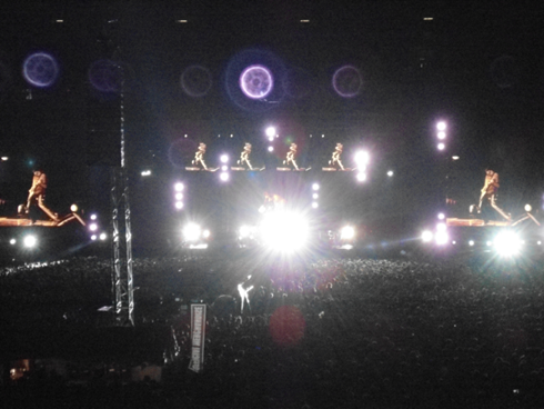

In the example above two photos were taken from the same location. The first photo was taken in the late afternoon, the second once it was dark. The resulting blended image appears to show the time of day being closer to sundown than in the first photo. The darker colours from the second photo are mostly excluded by the filter, lighter elements such as the stage lighting appear pronounced as a yellow tint in the output image.
The filter values specified are listed below as Xml. To reproduce the filter you can copy the Xml markup and save to disk specifying the file extension *.xbmp.
<?xml version="1.0" encoding="utf-8"?>
<BitmapFilterData xmlns:xsi="http://www.w3.org/2001/XMLSchema-instance" xmlns:xsd="http://www.w3.org/2001/XMLSchema">
  <SourceBlueEnabled>true</SourceBlueEnabled>
  <SourceGreenEnabled>true</SourceGreenEnabled>
  <SourceRedEnabled>true</SourceRedEnabled>
  <OverlayBlueEnabled>true</OverlayBlueEnabled>
  <OverlayGreenEnabled>true</OverlayGreenEnabled>
  <OverlayRedEnabled>true</OverlayRedEnabled>
  <SourceBlueLevel>0.5</SourceBlueLevel>
  <SourceGreenLevel>0.3</SourceGreenLevel>
  <SourceRedLevel>0.2</SourceRedLevel>
  <OverlayBlueLevel>0.75</OverlayBlueLevel>
  <OverlayGreenLevel>0.5</OverlayGreenLevel>
  <OverlayRedLevel>0.6</OverlayRedLevel>
  <BlendTypeBlue>Subtract</BlendTypeBlue>
  <BlendTypeGreen>Add</BlendTypeGreen>
  <BlendTypeRed>Add</BlendTypeRed>
</BitmapFilterData>
Blending two night time images:


Fun Fact: In this article some of the photos featured were taken at a live concert of The Red Hot Chilli Peppers, performing at Soccer City, Johannesburg, South Africa.
Related Articles

