Posts Tagged 'Gradient Edge Detection'

C# How to: Stained Glass Image Filter

Article Purpose

This article serves to provides a detailed discussion and implementation of a Stained Glass Image Filter. Primary topics explored include: Creating , Pixel Coordinate distance calculations implementing , and methods. In addition, this article explores Gradient Based implementing thresholds.

Zurich: Block Size 15, Factor 4, Euclidean

Zurich Block Size 15 Factor 4 Euclidean

Sample Source Code

This article is accompanied by a sample source code Visual Studio project which is available for download .

Using the Sample Application

This article’s accompanying sample source code includes a based sample application. The sample application provides an implementation of the concepts explored by this article. Concepts discussed can be easily replicated and tested by using the sample application.

Source/input files can be specified from the local system when clicking the Load Image button. Additionally users also have the option to save resulting filtered by clicking the Save Image button.

The sample application through its user interface allows a user to specify several filter configuration options. Two main categories of configuration options have been defined as Block Properties and Edge Properties.

Block Properties relate to  the process of rendering  . The following configuration options have been implemented:

  • Block Size – During the process of rendering a regions or blocks of equal shape and size have to be defined. These uniform regions/blocks form the basis of rendering uniquely shaped regions later on. The Block Size option determines the width and height of an individual region/block. Larger values result in larger non-uniform regions being rendered. Smaller values in return result in smaller non-uniform regions being rendered.
  • Distance Factor – The Distance Factor option determines the extent to which a pixel’s containing region will be calculated. Possible values range from 1 to 4 inclusive. A Distance Factor value of 4 equates to precise calculation of a pixel’s containing region, whereas a value of 1 results in containing regions often registering pixels that should be part of a neighbouring region. Values closer to 4 result in more varied region shapes. Values closer to 1 result in regions being rendered having more of a uniform shape/pattern.
  • Distance Formula – The distance between a pixel’s coordinates and a region’s outline determines whether that pixel should be considered part of a region. The sample application implements three different methods of calculating pixel distance: , and methods. Each result in region shapes being rendered differently.

Salzburg: Block Size 20, Factor 1, Chebyshev, Edge Threshold 2 

Saltzburg Block Size 20 Factor 1 Chebyshev Edge Threshold 2

Edge Properties relate to the implementation of Image Gradient Based Edge Detection. is an optional filter and can be enabled/disabled through the user interface, The implementation of serves to highlight/outline regions rendered as part of a . The configuration options implemented are:

  • Highlight Edges – Boolean value indicating whether or not should be applied
  • Threshold – In calculating a threshold value determines if a pixel forms part of an edge. Higher threshold values result in less being expressed. Lower threshold values result in more being expressed.
  • Colour – If a pixel has been determined as forming part of an , the resulting pixel colour will be determined by the colour value specified by the user.

The following image is a screenshot of the Stained Glass Image Filter sample application in action:

Stained Glass Image Filter Sample Application 

Locarno: Block Size 10, Factor 4, Euclidean

Locarno Block Size 10 Factor 4 Euclidean

Stained Glass

The Stained Glass Image Filter detailed in this article operates on the basis of implementing modifications upon a specified sample/input , producing resulting which resemble the appearance of stained glass artwork.

A common variant of stained glass artwork comes in the form of several individual pieces of coloured glass being combined in order to create an . The sample source code employs a similar  method of combining what appears to be non-uniform puzzle pieces. The following list provides a broad overview of the steps involved in applying a Stained Glass Image Filter:

  1. Render a Voronoi Diagram – Through rendering a the resulting will be divided into a number of regions. Each region being intended to represent an individual glass puzzle piece. The following section of this article provides a detailed discussion on rendering .
  2. Assign each Pixel to a Voronoi Diagram Region – Each pixel forming part of the source/input should be iterated. Whilst iterating pixels determine the region to which a pixel should be associated. A pixel should be associated to the region whose border has been determined the nearest to the pixel. In a following section of this article a detailed discussion regarding Pixel Coordinate Distance Calculations can be found.
  3. Determine each Region’s Colour Mean – Each region will only express a single colour value. A region’s colour equates to the average colour as expressed by all the pixels forming part of a region. Once the average colour value of a region has been determined every pixel forming part of that region should be set to the average colour.
  4. Implement Edge Detection – If the user configuration option indicates that should be implemented, apply Gradient Based Edge Detection. This method of has been discussed in detailed in a following section of this article.

Bad Ragaz: Block Size 10, Factor 1, Manhattan 

Bad Ragaz Block Size 10 Factor 1 Manhattan

Voronoi Diagrams

represent a fairly uncomplicated concept. In contrast, the implementation of prove somewhat more of a challenge. From we gain the following :

In mathematics, a Voronoi diagram is a way of dividing space into a number of regions. A set of points (called seeds, sites, or generators) is specified beforehand and for each seed there will be a corresponding region consisting of all points closer to that seed than to any other. The regions are called Voronoi cells. It is dual to the Delaunay triangulation.

In this article are generated resulting in regions expressing random shapes. Although region shapes are randomly generated, the parameters or ranges within which random values are selected are fixed/constant. The steps required in generating a can be detailed as follows:

  1. Define fixed size square regions – By making use of the user specified Block/Region Size value, group pixels together into square regions.
  2. Determine a Seed Value for Random number generation – Determine the sum total of pixel colour components of all the pixels forming part of a square region. The colour sum total value should be used as a seed value when generating random numbers in the next step.
  3. Determine a Random XY coordinate within each square region – Generate two random numbers, specifying each region’s coordinate boundaries as minimum and maximum boundaries in generating random numbers. Keep record of every new randomly generated XY-Coordinate value.
  4. Associate Pixels and Regions – A pixel should be associated to the Random Coordinate point nearest to that pixel. Determine the Random Coordinate nearest to each pixel in the source/input image. The method implemented in calculating coordinate distance depends on the configuration value specified by the user.
  5. Set Region Colours – Each pixel forming part of the same region should be set to the same colour. The colour assigned to a region’s pixels will be determined by the average colour value of the region’s pixels.

The following image illustrates an example consisting of 10 regions:

2Ddim-L2norm-10site

Port Edward: Block Size 10, Factor 1, Chebyshev, Edge Threshold 2

Port Edward Block Size 10 Factor 1 Chebyshev Edge Threshold 2

Calculating Pixel Coordinate Distances

The sample source code provides three different coordinate distance calculation methods. The supported methods are: , and . A pixel’s nearest randomly generated coordinate depends on the distance between that pixel and the random coordinate. Each method of calculating distance in most instances would be likely to produce different output values, which in turn influences the region to which a pixel will be associated.

The most common method of distance calculation, , has been described by as follows:

In mathematics, the Euclidean distance or Euclidean metric is the "ordinary" distance between two points that one would measure with a ruler, and is given by the Pythagorean formula. By using this formula as distance, Euclidean space (or even any inner product space) becomes a metric space. The associated norm is called the Euclidean norm. Older literature refers to the metric as Pythagorean metric.

When calculating the algorithm implemented can be expressed as follows:

Euclidean Distance Algorithm

Zurich: Block Size 10, Factor 1, Euclidean

Zurich Block Size 10 Factor 1 Euclidean

As an alternative to calculating , the sample source code also implements calculation. Often calculation will be referred to as , or . From we gain the following :

Taxicab geometry, considered by Hermann Minkowski in the 19th century, is a form of geometry in which the usual distance function or metric of Euclidean geometry is replaced by a new metric in which the distance between two points is the sum of the absolute differences of their coordinates. The taxicab metric is also known as rectilinear distance, L1 distance or \ell_1 norm (see Lp space), city block distance, Manhattan distance, or Manhattan length, with corresponding variations in the name of the geometry.[1] The latter names allude to the grid layout of most streets on the island of Manhattan, which causes the shortest path a car could take between two intersections in the borough to have length equal to the intersections’ distance in taxicab geometry

When calculating the algorithm implemented can be expressed as follows:

Manhattan Distance Algorithm

Port Edward: Block Size 10, Factor 4, Euclidean

Port Edward Block Size 10 Factor 4 Euclidean

, a distance algorithm resembling the way in which a King Chess piece may move on a chess board. The following we gain from :

In mathematics, Chebyshev distance (or Tchebychev distance), Maximum metric, or L∞ metric[1] is a metric defined on a vector space where the distance between two vectors is the greatest of their differences along any coordinate dimension.[2] It is named after Pafnuty Chebyshev.

It is also known as chessboard distance, since in the game of chess the minimum number of moves needed by a king to go from one square on a chessboard to another equals the Chebyshev distance between the centers of the squares, if the squares have side length one, as represented in 2-D spatial coordinates with axes aligned to the edges of the board.[3] For example, the Chebyshev distance between f6 and e2 equals 4.

When calculating the algorithm implemented can be expressed as follows:

Chebyshev Distance Algorithm

Salzburg: Block Size 20, Factor 1, Chebyshev

Salzburg Block Size 20 Factor 1 Chebyshev

Gradient Based Edge Detection

Various methods of can easily be implemented in C#. Each method of provides a set of benefits, usually weighed against a set of trade-offs. In this article and the accompanying sample source code the Gradient Based Edge Detection method has been implement.

Take into regard that every region within the rendered will only express a single colour, although most regions differ in the single colour they express. Once all pixels have been associated to a region and all pixel colour values have been updated the resulting defines mostly clearly distinguishable  colour gradients. A method of performs efficiently at detecting . The edges detected are defined between different regions.

An can be considered as a difference in colour intensity relating to a specific direction. Only once all tasks related to applying the Stained Glass Filter have been completed should the Gradient Based Edge Detection be applied. The steps involved in applying Gradient Based Edge Detection can be described as follows:

  1. Iterate each pixel – Each pixel forming part of a source/input image should be iterated.
  2. Determine Horizontal and Vertical Gradients – Calculate the colour value difference between the currently iterated pixel’s left and right neighbour pixel as well as the top and bottom neighbour pixel. If the gradient exceeds the specified threshold continue to step 8.
  3. Determine Horizontal Gradient – Calculate the colour value difference between the currently iterated pixel’s left and right neighbour pixel. If the gradient exceeds the specified threshold continue to step 8.
  4. Determine Vertical Gradient – Calculate the colour value difference between the currently iterated pixel’s top and bottom neighbour pixel. If the gradient exceeds the specified threshold continue to step 8.
  5. Determine Diagonal Gradients – Calculate the colour value difference between the currently iterated pixel’s North-Western and South-Eastern neighbour pixel as well as the North-Eastern and South-Western neighbour pixel. If the gradient exceeds the specified threshold continue to step 8.
  6. Determine NW-SE Gradient – Calculate the colour value difference between the currently iterated pixel’s North-Western and South-Eastern neighbour pixel. If the gradient exceeds the specified threshold continue to step 8.
  7. Determine NE-SW Gradient  – Calculate the colour value difference between the currently iterated pixel’s North-Eastern and South-Western neighbour pixel.
  8. Determine and set result pixel value – If any of the six gradients calculated exceeded the specified threshold value set the related pixel in the resulting image to the Edge Colour specified by the user, if not, set the related pixel equal to the source pixel colour value.

Zurich: Block Size 10, Factor 4, Chebyshev

Zurich Block Size 10 Factor 4 Chebyshev 

Implementing a Stained Glass Image Filter

The sample source code defines two helper classes, both implemented when applying the Stained Glass Image Filter. The Pixel class represents a single pixel in terms of an XY-Coordinate and Red, Green and Blue values. The definition as follows:

public class Pixel  
{
    private int xOffset = 0; 
    public int XOffset 
    {
        get { return xOffset; } set { xOffset = value; } 
    }

private int yOffset = 0; public int YOffset { get { return yOffset; } set { yOffset = value; } }
private byte blue = 0; public byte Blue { get { return blue; } set { blue = value; } }
private byte green = 0; public byte Green { get { return green; } set { green = value; } }
private byte red = 0; public byte Red { get { return red; } set { red = value; } } }

Zurich: Block Size 10, Factor 1, Chebyshev, Edge Threshold 1

Zurich Block Size 10 Factor 1 Chebyshev Edge Threshold 1

The VoronoiPoint class serves as method of recording randomly generated coordinates and referencing a region’s associated pixels. The definition as follows:

public class VoronoiPoint 
{
    private int xOffset = 0; 
    public int XOffset 
    {
        get  { return xOffset; } set { xOffset = value; }
    }

private int yOffset = 0; public int YOffset { get { return yOffset; } set { yOffset = value; } }
private int blueTotal = 0; public int BlueTotal { get { return blueTotal; } set { blueTotal = value; } }
private int greenTotal = 0; public int GreenTotal { get {return greenTotal; } set { greenTotal = value; } }
private int redTotal = 0; public int RedTotal { get { return redTotal; } set { redTotal = value; } }
public void CalculateAverages() { if (pixelCollection.Count > 0) { blueAverage = blueTotal / pixelCollection.Count; greenAverage = greenTotal / pixelCollection.Count; redAverage = redTotal / pixelCollection.Count; } }
private int blueAverage = 0; public int BlueAverage { get { return blueAverage; } }
private int greenAverage = 0; public int GreenAverage { get { return greenAverage; } }
private int redAverage = 0; public int RedAverage { get { return redAverage; } }
private List<Pixel> pixelCollection = new List<Pixel>(); public List<Pixel> PixelCollection { get { return pixelCollection; } }
public void AddPixel(Pixel pixel) { blueTotal += pixel.Blue; greenTotal += pixel.Green; redTotal += pixel.Red;
pixelCollection.Add(pixel); } }

Zurich: Block Size 20, Factor 1, Euclidean, Edge Threshold 1

Zurich Block Size 20 Factor 1 Euclidean Edge Threshold 1

From the perspective of a filter implementation code base the only requirement comes in the form of having to invoke the StainedGlassColorFilter , no additional work is required from external code consumers. The StainedGlassColorFilter method has been defined as an targeting the class. The StainedGlassColorFilter method definition as follows:

public static Bitmap StainedGlassColorFilter(this Bitmap sourceBitmap,  
                                             int blockSize, double blockFactor, 
                                             DistanceFormulaType distanceType, 
                                             bool highlightEdges,  
                                             byte edgeThreshold, Color edgeColor) 
{
    BitmapData sourceData = 
               sourceBitmap.LockBits(new Rectangle(0, 0, 
               sourceBitmap.Width, sourceBitmap.Height), 
               ImageLockMode.ReadOnly, 
               PixelFormat.Format32bppArgb); 

byte[] pixelBuffer = new byte[sourceData.Stride * sourceData.Height];
byte[] resultBuffer = new byte[sourceData.Stride * sourceData.Height];
Marshal.Copy(sourceData.Scan0, pixelBuffer, 0, pixelBuffer.Length);
sourceBitmap.UnlockBits(sourceData);
int neighbourHoodTotal = 0; int sourceOffset = 0; int resultOffset = 0; int currentPixelDistance = 0; int nearestPixelDistance = 0; int nearesttPointIndex = 0;
Random randomizer = new Random();
List<VoronoiPoint> randomPointList = new List<VoronoiPoint>();
for (int row = 0; row < sourceBitmap.Height - blockSize; row += blockSize) { for (int col = 0; col < sourceBitmap.Width - blockSize; col += blockSize) { sourceOffset = row * sourceData.Stride + col * 4;
neighbourHoodTotal = 0;
for (int y = 0; y < blockSize; y++) { for (int x = 0; x < blockSize; x++) { resultOffset = sourceOffset + y * sourceData.Stride + x * 4; neighbourHoodTotal += pixelBuffer[resultOffset]; neighbourHoodTotal += pixelBuffer[resultOffset + 1]; neighbourHoodTotal += pixelBuffer[resultOffset + 2]; } }
randomizer = new Random(neighbourHoodTotal);
VoronoiPoint randomPoint = new VoronoiPoint(); randomPoint.XOffset = randomizer.Next(0, blockSize) + col; randomPoint.YOffset = randomizer.Next(0, blockSize) + row;
randomPointList.Add(randomPoint); } }
int rowOffset = 0; int colOffset = 0;
for (int bufferOffset = 0; bufferOffset < pixelBuffer.Length - 4; bufferOffset += 4) { rowOffset = bufferOffset / sourceData.Stride; colOffset = (bufferOffset % sourceData.Stride) / 4;
currentPixelDistance = 0; nearestPixelDistance = blockSize * 4; nearesttPointIndex = 0;
List<VoronoiPoint> pointSubset = new List<VoronoiPoint>();
pointSubset.AddRange(from t in randomPointList where rowOffset >= t.YOffset - blockSize * 2 && rowOffset <= t.YOffset + blockSize * 2 select t);
for (int k = 0; k < pointSubset.Count; k++) { if (distanceType == DistanceFormulaType.Euclidean) { currentPixelDistance = CalculateDistanceEuclidean(pointSubset[k].XOffset, colOffset, pointSubset[k].YOffset, rowOffset); } else if (distanceType == DistanceFormulaType.Manhattan) { currentPixelDistance = CalculateDistanceManhattan(pointSubset[k].XOffset, colOffset, pointSubset[k].YOffset, rowOffset); } else if (distanceType == DistanceFormulaType.Chebyshev) { currentPixelDistance = CalculateDistanceChebyshev(pointSubset[k].XOffset, colOffset, pointSubset[k].YOffset, rowOffset); } if (currentPixelDistance <= nearestPixelDistance) { nearestPixelDistance = currentPixelDistance; nearesttPointIndex = k; if (nearestPixelDistance <= blockSize / blockFactor) { break; } } }
Pixel tmpPixel = new Pixel (); tmpPixel.XOffset = colOffset; tmpPixel.YOffset = rowOffset; tmpPixel.Blue = pixelBuffer[bufferOffset]; tmpPixel.Green = pixelBuffer[bufferOffset + 1]; tmpPixel.Red = pixelBuffer[bufferOffset + 2];
pointSubset[nearesttPointIndex].AddPixel(tmpPixel); }
for (int k = 0; k < randomPointList.Count; k++) { randomPointList[k].CalculateAverages();
for (int i = 0; i < randomPointList[k].PixelCollection.Count; i++) { resultOffset = randomPointList[k].PixelCollection[i].YOffset * sourceData.Stride + randomPointList[k].PixelCollection[i].XOffset * 4;
resultBuffer[resultOffset] = (byte)randomPointList[k].BlueAverage; resultBuffer[resultOffset + 1] = (byte)randomPointList[k].GreenAverage; resultBuffer[resultOffset + 2] = (byte)randomPointList[k].RedAverage;
resultBuffer[resultOffset + 3] = 255; } }
Bitmap resultBitmap = new Bitmap(sourceBitmap.Width, sourceBitmap.Height);
BitmapData resultData = resultBitmap.LockBits(new Rectangle (0, 0, resultBitmap.Width, resultBitmap.Height), ImageLockMode.WriteOnly, PixelFormat.Format32bppArgb);
Marshal.Copy(resultBuffer, 0, resultData.Scan0, resultBuffer.Length);
resultBitmap.UnlockBits(resultData);
if (highlightEdges == true ) { resultBitmap = resultBitmap.GradientBasedEdgeDetectionFilter(edgeColor, edgeThreshold); }
return resultBitmap; }

Locarno: Block Size 10, Factor 4, Euclidean, Edge Threshold 1

Locarno Block Size 10 Factor 4 Euclidean Edge Threshold 1

Implementing Pixel Coordinate Distance Calculations

As mentioned earlier, this article and the accompanying sample source code support coordinate distance calculations through three different calculation methods, namely , and . The method of distance calculation implemented depends on the configuration option specified by the user.

The CalculateDistanceEuclidean method calculates distance implementing the Calculation method. In order to aid faster execution this method will calculate the square root of a specific value only once. Once a square root has been calculated the result is kept in memory. The following code snippet lists the definition of the CalculateDistanceEuclidean method:

private static Dictionary <int,int> squareRoots = new Dictionary<int,int>(); 

private static int CalculateDistanceEuclidean(int x1, int x2, int y1, int y2) { int square = (x1 - x2) * (x1 - x2) + (y1 - y2) * (y1 - y2);
if(squareRoots.ContainsKey(square) == false) { squareRoots.Add(square, (int)Math.Sqrt(square)); }
return squareRoots[square]; }

The two other methods of calculating distance are implemented through the CalculateDistanceManhattan and CalculateDistanceChebyshev methods. The definition as follows:

private static int CalculateDistanceManhattan(int x1, int x2, int y1, int y2) 
{
    return Math.Abs(x1 - x2) + Math.Abs(y1 - y2); 
}

private static int CalculateDistanceChebyshev(int x1, int x2, int y1, int y2) { return Math.Max(Math.Abs(x1 - x2), Math.Abs(y1 - y2)); }

Bad Ragaz: Block Size 12, Factor 1, Chebyshev

Bad Ragaz Block Size 12 Factor 1 Chebyshev

Implementing Gradient Based Edge Detection

Did you notice the very last step performed by the StainedGlassColorFilter method involves implementing Gradient Based Edge Detection, depending on whether had been specified by the user.

The following code snippet provides the implementation of the GradientBasedEdgeDetectionFilter extension method:

public static Bitmap GradientBasedEdgeDetectionFilter( 
                this Bitmap sourceBitmap, 
                Color edgeColour, 
                byte threshold = 0) 
{
    BitmapData sourceData = 
               sourceBitmap.LockBits(new Rectangle (0, 0, 
               sourceBitmap.Width, sourceBitmap.Height), 
               ImageLockMode.ReadOnly, 
               PixelFormat.Format32bppArgb); 

byte[] pixelBuffer = new byte[sourceData.Stride * sourceData.Height]; byte[] resultBuffer = new byte[sourceData.Stride * sourceData.Height];
Marshal.Copy(sourceData.Scan0, pixelBuffer, 0, pixelBuffer.Length); Marshal.Copy(sourceData.Scan0, resultBuffer, 0, resultBuffer.Length);
sourceBitmap.UnlockBits(sourceData);
int sourceOffset = 0, gradientValue = 0; bool exceedsThreshold = false;
for(int offsetY = 1; offsetY < sourceBitmap.Height - 1; offsetY++) { for(int offsetX = 1; offsetX < sourceBitmap.Width - 1; offsetX++) { sourceOffset = offsetY * sourceData.Stride + offsetX * 4; gradientValue = 0; exceedsThreshold = true;
// Horizontal Gradient CheckThreshold(pixelBuffer, sourceOffset - 4, sourceOffset + 4, ref gradientValue, threshold, 2); // Vertical Gradient exceedsThreshold = CheckThreshold(pixelBuffer, sourceOffset - sourceData.Stride, sourceOffset + sourceData.Stride, ref gradientValue, threshold, 2);
if (exceedsThreshold == false) { gradientValue = 0;
// Horizontal Gradient exceedsThreshold = CheckThreshold(pixelBuffer, sourceOffset - 4, sourceOffset + 4, ref gradientValue, threshold);
if (exceedsThreshold == false) { gradientValue = 0;
// Vertical Gradient exceedsThreshold = CheckThreshold(pixelBuffer, sourceOffset - sourceData.Stride, sourceOffset + sourceData.Stride, ref gradientValue, threshold);
if (exceedsThreshold == false) { gradientValue = 0;
// Diagonal Gradient : NW-SE CheckThreshold(pixelBuffer, sourceOffset - 4 - sourceData.Stride, sourceOffset + 4 + sourceData.Stride, ref gradientValue, threshold, 2); // Diagonal Gradient : NE-SW exceedsThreshold = CheckThreshold(pixelBuffer, sourceOffset - sourceData.Stride + 4, sourceOffset - 4 + sourceData.Stride, ref gradientValue, threshold, 2);
if (exceedsThreshold == false) { gradientValue = 0;
// Diagonal Gradient : NW-SE exceedsThreshold = CheckThreshold(pixelBuffer, sourceOffset - 4 - sourceData.Stride, sourceOffset + 4 + sourceData.Stride, ref gradientValue, threshold);
if (exceedsThreshold == false) { gradientValue = 0;
// Diagonal Gradient : NE-SW exceedsThreshold = CheckThreshold(pixelBuffer, sourceOffset - sourceData.Stride + 4, sourceOffset + sourceData.Stride - 4, ref gradientValue, threshold); } } } } }
if (exceedsThreshold == true) { resultBuffer[sourceOffset] = edgeColour.B; resultBuffer[sourceOffset + 1] = edgeColour.G; resultBuffer[sourceOffset + 2] = edgeColour.R; }
resultBuffer[sourceOffset + 3] = 255; } }
Bitmap resultBitmap = new Bitmap (sourceBitmap.Width, sourceBitmap.Height); BitmapData resultData = resultBitmap.LockBits(new Rectangle (0, 0, resultBitmap.Width, resultBitmap.Height), ImageLockMode .WriteOnly, PixelFormat.Format32bppArgb);
Marshal.Copy(resultBuffer, 0, resultData.Scan0, resultBuffer.Length); resultBitmap.UnlockBits(resultData);
return resultBitmap; }

Zurich: Block Size 15, Factor 1, Manhattan, Edge Threshold 1

Zurich Block Size 15 Factor 1 Manhattan Edge Threshold 1

Sample Images

This article features a rendered graphic illustrating an example which has been released into the public domain by its author, Augochy at the wikipedia project. This applies worldwide. The original can be downloaded from .

All of the photos that appear in this article were taken by myself. Photos listed under Zurich, Locarno and Bad Ragaz were shot in Switzerland. The photo listed as Salzburg had been shot in Austria and the photo listed under Port Edward had been shot in South Africa. In order to fully realize the extent to which had been modified the following section details the original photos.

Zurich, Switzerland

Zurich, Switzerland

Salzburg, Austria

Salzburg, Austria

Locarno, Switzerland

Locarno, Switzerland

Bad Ragaz, Switzerland

Bad Ragaz, Switzerland

Port Edward, South Africa

Port Edward, South Africa

Zurich, Switzerland

Zurich, Switzerland

Zurich, Switzerland

Zurich, Switzerland

Zurich, Switzerland

Zurich, Switzerland

Bad Ragaz, Switzerland

Bad Ragaz, Switzerland

Related Articles and Feedback

Feedback and questions are always encouraged. If you know of an alternative implementation or have ideas on a more efficient implementation please share in the comments section.

I’ve published a number of articles related to imaging and images of which you can find URL links here:

C# How to: Oil Painting and Cartoon Filter

Article Purpose

This article illustrates and provides a discussion and implementation of Oil Painting Filters and related Image Cartoon Filters.

Sunflower: Oil Painting, Filter 5, Levels 30, Cartoon Threshold 30

Sunflower Oil Painting Filter 5 Levels 30 Cartoon Threshold 30

Sample Source Code

This article is accompanied by a sample source code Visual Studio project which is available for download .

Using the Sample Application

A sample application accompanies this article. The sample application creates a visual implementation of the concepts discussed throughout this article. Source/input can be selected from the local system and if desired filter result images can be saved to the local file system.

The two main types of functionality exposed by the sample application can be described as Image Oil Painting Filters and Image Cartoon Filters. The user interface provides the following user input options:

  • Filter Size – The number of neighbouring pixels used in calculating each individual pixel value in regards to an Oil Painting Filter. Higher Filter sizes relate to a more intense Oil Painting Filter being applied. Lower Filter sizes relate to less intense Oil Painting Filters being applied.
  • Intensity Levels – Represents the number of Intensity Levels implemented when applying an Oil Painting Filter. Higher values result in a broader range of colour intensities forming part of the result . Lower values will reduce the range of colour intensities forming part of the result .
  • Cartoon Filter – A Boolean value indicating whether or not in addition to an Oil Painting Filter if a Cartoon Filter should also be applied.
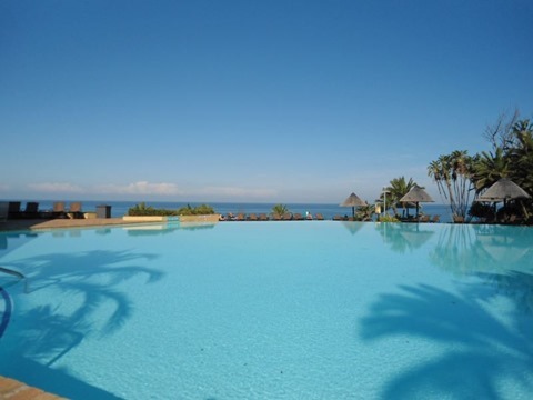
  • Threshold – Only applicable when applying a Cartoon Filter. This option represents the threshold value implemented in determining whether a pixel forms part of an . Lower Values result in more being highlighted. Higher values result in less being highlighted.

The following image is screenshot of the Oil Painting Cartoon Filter sample application in action:

OilPaintingCartoonFilter_SampleApplication

Rose: Oil Painting, Filter 15, Levels 10

Rose Oil Painting Filter 15 Levels 10

Image Oil Painting Filter

The Image Oil Painting Filter consists of two main components: colour gradients and pixel colour intensities. As implied by the title when implementing this resulting are similar in appearance to of Oil Paintings. Result express a lesser degree of detail when compared to source/input . This filter also tends to output which appear to have smaller colour ranges.

Four steps are required when implementing an Oil Painting Filter, indicated as follows:

  1. Iterate each pixel – Every pixel forming part of the source/input should be iterated. When iterating a pixel determine the neighbouring pixel values based on the specified filter size/filter range.
  2. Calculate Colour Intensity -  Determine the Colour Intensity of each pixel being iterated and that of the neighbouring pixels. The neighbouring pixels included should extend to a range determined by the Filter Size specified. The calculated value should be reduced in order to match a value ranging from zero to the number of Intensity Levels specified.
  3. Determine maximum neighbourhood colour intensity – When calculating the colour intensities of a pixel neighbourhood determine the maximum intensity value. In addition, record the occurrence of each intensity level and sum each of the Red, Green and Blue pixel colour component values equating to the same intensity level.
  4. Assign the result pixel – The value assigned to the corresponding pixel in the resulting equates to the pixel colour sum total, where those pixels expressed the same intensity level. The sum total should be averaged by dividing the colour sum total by the intensity level occurrence.

Roses: Oil Painting, Filter 11, Levels 60, Cartoon Threshold 80

Roses Oil Painting Filter 11 Levels 60 Cartoon Threshold 80

When calculating colour intensity reduced to fit the number of levels specified  the algorithm implemented can be expressed as follows:

Colour Intensity Level Algorithm

In the algorithm listed above the variables implemented can be explained as follows:

  • I – Intensity: The calculated intensity value.
  • R – Red: The value of a pixel’s Red colour component.
  • G – Green: The value of a pixel’s Green colour component.
  • B – Blue: The value of a pixel’s Blue colour component.
  • l – Number of intensity levels: The maximum number of intensity levels specified.

Rose: Oil Painting, Filter 15, Levels 30

Rose Oil Painting Filter 15 Levels 30

Cartoon Filter implementing Edge Detection

A Cartoon Filter effect can be achieved by combining an Image Oil Painting filter and an Edge Detection Filter. The Oil Painting filter has the effect of creating more gradual colour gradients, in other words reducing edge intensity.

The steps required in implementing a Cartoon filter can be listed as follows:

  1. Apply Oil Painting filter – Applying an Oil Painting Filter creates the perception of result having been painted by hand.
  2. Implement Edge Detection – Using the original source/input create a new binary detailing .
  3. Overlay edges on Oil Painting image – Iterate each pixel forming part of the edge detected . If the pixel being iterated forms part of an edge, the related pixel in the Oil Painting filtered should be set to black. Because the edge detected was created as a binary , a pixel forms part of an edge should that pixel equate to white.

Daisy: Oil Painting, Filter 7, Levels 30, Cartoon Threshold 40 

Daisy Oil Painting Filter 7 Levels 30 Cartoon Threshold 40

In the sample source code has been implemented through Gradient Based Edge Detection. This method of compares the difference in colour gradients between a pixel’s neighbouring pixels. A pixel forms part of an edge if the difference in neighbouring pixel colour values exceeds a specified threshold value. The steps involved in Gradient Based Edge Detection as follows:

  1. Iterate each pixel – Each pixel forming part of a source/input should be iterated.
  2. Determine Horizontal and Vertical Gradients – Calculate the colour value difference between the currently iterated pixel’s left and right neighbour pixel as well as the top and bottom neighbour pixel. If the gradient exceeds the specified threshold continue to step 8.
  3. Determine Horizontal Gradient – Calculate the colour value difference between the currently iterated pixel’s left and right neighbour pixel. If the gradient exceeds the specified threshold continue to step 8.
  4. Determine Vertical Gradient – Calculate the colour value difference between the currently iterated pixel’s top and bottom neighbour pixel. If the gradient exceeds the specified threshold continue to step 8.
  5. Determine Diagonal Gradients – Calculate the colour value difference between the currently iterated pixel’s North-Western and South-Eastern neighbour pixel as well as the North-Eastern and South-Western neighbour pixel. If the gradient exceeds the specified threshold continue to step 8.
  6. Determine NW-SE Gradient – Calculate the colour value difference between the currently iterated pixel’s North-Western and South-Eastern neighbour pixel. If the gradient exceeds the specified threshold continue to step 8.
  7. Determine NE-SW Gradient  – Calculate the colour value difference between the currently iterated pixel’s North-Eastern and South-Western neighbour pixel.
  8. Determine and set result pixel value – If any of the six gradients calculated exceeded the specified threshold value set the related pixel in the resulting image to white, if not, set the related pixel to black.

Rose: Oil Painting, Filter 9, Levels 30

Rose Oil Painting Filter 9 Levels 30

Implementing an Oil Painting Filter

The sample source code defines the OilPaintFilter method, an targeting the class. method determines the maximum colour intensity from a pixel’s neighbouring pixels. The definition detailed as follows:

public static Bitmap OilPaintFilter(this Bitmap sourceBitmap, 
                                       int levels, 
                                       int filterSize) 
{
    BitmapData sourceData = 
               sourceBitmap.LockBits(new Rectangle(0, 0, 
               sourceBitmap.Width, sourceBitmap.Height), 
               ImageLockMode.ReadOnly, 
               PixelFormat.Format32bppArgb); 

byte[] pixelBuffer = new byte[sourceData.Stride * sourceData.Height];
byte[] resultBuffer = new byte[sourceData.Stride * sourceData.Height];
Marshal.Copy(sourceData.Scan0, pixelBuffer, 0, pixelBuffer.Length);
sourceBitmap.UnlockBits(sourceData);
int[] intensityBin = new int [levels]; int[] blueBin = new int [levels]; int[] greenBin = new int [levels]; int[] redBin = new int [levels];
levels = levels - 1;
int filterOffset = (filterSize - 1) / 2; int byteOffset = 0; int calcOffset = 0; int currentIntensity = 0; int maxIntensity = 0; int maxIndex = 0;
double blue = 0; double green = 0; double red = 0;
for (int offsetY = filterOffset; offsetY < sourceBitmap.Height - filterOffset; offsetY++) { for (int offsetX = filterOffset; offsetX < sourceBitmap.Width - filterOffset; offsetX++) { blue = green = red = 0;
currentIntensity = maxIntensity = maxIndex = 0;
intensityBin = new int[levels + 1]; blueBin = new int[levels + 1]; greenBin = new int[levels + 1]; redBin = new int[levels + 1];
byteOffset = offsetY * sourceData.Stride + offsetX * 4;
for (int filterY = -filterOffset; filterY <= filterOffset; filterY++) { for (int filterX = -filterOffset; filterX <= filterOffset; filterX++) { calcOffset = byteOffset + (filterX * 4) + (filterY * sourceData.Stride);
currentIntensity = (int )Math.Round(((double) (pixelBuffer[calcOffset] + pixelBuffer[calcOffset + 1] + pixelBuffer[calcOffset + 2]) / 3.0 * (levels)) / 255.0);
intensityBin[currentIntensity] += 1; blueBin[currentIntensity] += pixelBuffer[calcOffset]; greenBin[currentIntensity] += pixelBuffer[calcOffset + 1]; redBin[currentIntensity] += pixelBuffer[calcOffset + 2];
if (intensityBin[currentIntensity] > maxIntensity) { maxIntensity = intensityBin[currentIntensity]; maxIndex = currentIntensity; } } }
blue = blueBin[maxIndex] / maxIntensity; green = greenBin[maxIndex] / maxIntensity; red = redBin[maxIndex] / maxIntensity;
resultBuffer[byteOffset] = ClipByte(blue); resultBuffer[byteOffset + 1] = ClipByte(green); resultBuffer[byteOffset + 2] = ClipByte(red); resultBuffer[byteOffset + 3] = 255; } }
Bitmap resultBitmap = new Bitmap(sourceBitmap.Width, sourceBitmap.Height);
BitmapData resultData = resultBitmap.LockBits(new Rectangle(0, 0, resultBitmap.Width, resultBitmap.Height), ImageLockMode.WriteOnly, PixelFormat.Format32bppArgb);
Marshal.Copy(resultBuffer, 0, resultData.Scan0, resultBuffer.Length);
resultBitmap.UnlockBits(resultData);
return resultBitmap; }

Rose: Oil Painting, Filter 7, Levels 20, Cartoon Threshold 20

Rose Oil Painting Filter 7 Levels 20 Cartoon Threshold 20

Implementing a Cartoon Filter using Edge Detection

The sample source code defines the CheckThreshold method. The purpose of this method to determine the difference in colour between two pixels. In addition this method compares the colour difference and the specified threshold value. The following code snippet provides the implementation:

private static bool CheckThreshold(byte[] pixelBuffer,  
                                   int offset1, int offset2,  
                                   ref int gradientValue,  
                                   byte threshold,  
                                   int divideBy = 1) 
{ 
    gradientValue += 
    Math.Abs(pixelBuffer[offset1] - 
    pixelBuffer[offset2]) / divideBy; 

gradientValue += Math.Abs(pixelBuffer[offset1 + 1] - pixelBuffer[offset2 + 1]) / divideBy;
gradientValue += Math.Abs(pixelBuffer[offset1 + 2] - pixelBuffer[offset2 + 2]) / divideBy;
return (gradientValue >= threshold); }

Rose: Oil Painting, Filter 13, Levels 15

Rose Oil Painting Filter 13 Levels 15

The GradientBasedEdgeDetectionFilter method has been defined as an targeting the class. This method iterates each pixel forming part of the source/input . Whilst iterating pixels the GradientBasedEdgeDetectionFilter determines if the colour gradients in various directions exceeds the specified threshold value. A pixel is considered as part of an edge if a colour gradient exceeds the threshold value. The implementation as follows:

public static Bitmap GradientBasedEdgeDetectionFilter( 
                        this Bitmap sourceBitmap, 
                        byte threshold = 0) 
{ 
    BitmapData sourceData = 
               sourceBitmap.LockBits(new Rectangle (0, 0, 
               sourceBitmap.Width, sourceBitmap.Height), 
               ImageLockMode.ReadOnly, 
               PixelFormat.Format32bppArgb); 

byte[] pixelBuffer = new byte[sourceData.Stride * sourceData.Height]; byte[] resultBuffer = new byte[sourceData.Stride * sourceData.Height];
Marshal.Copy(sourceData.Scan0, pixelBuffer, 0, pixelBuffer.Length); sourceBitmap.UnlockBits(sourceData);
int sourceOffset = 0, gradientValue = 0; bool exceedsThreshold = false;
for(int offsetY = 1; offsetY < sourceBitmap.Height - 1; offsetY++) { for(int offsetX = 1; offsetX < sourceBitmap.Width - 1; offsetX++) { sourceOffset = offsetY * sourceData.Stride + offsetX * 4; gradientValue = 0; exceedsThreshold = true ;
// Horizontal Gradient CheckThreshold(pixelBuffer, sourceOffset - 4, sourceOffset + 4, ref gradientValue, threshold, 2); // Vertical Gradient exceedsThreshold = CheckThreshold(pixelBuffer, sourceOffset - sourceData.Stride, sourceOffset + sourceData.Stride, ref gradientValue, threshold, 2);
if (exceedsThreshold == false ) { gradientValue = 0;
// Horizontal Gradient exceedsThreshold = CheckThreshold(pixelBuffer, sourceOffset - 4, sourceOffset + 4, ref gradientValue, threshold);
if (exceedsThreshold == false ) { gradientValue = 0; // Vertical Gradient exceedsThreshold = CheckThreshold(pixelBuffer, sourceOffset - sourceData.Stride, sourceOffset + sourceData.Stride, ref gradientValue, threshold);
if (exceedsThreshold == false ) { gradientValue = 0; // Diagonal Gradient : NW-SE CheckThreshold(pixelBuffer, sourceOffset - 4 - sourceData.Stride, sourceOffset + 4 + sourceData.Stride, ref gradientValue, threshold, 2); // Diagonal Gradient : NE-SW exceedsThreshold = CheckThreshold(pixelBuffer, sourceOffset - sourceData.Stride + 4, sourceOffset - 4 + sourceData.Stride, ref gradientValue, threshold, 2);
if (exceedsThreshold == false ) { gradientValue = 0; // Diagonal Gradient : NW-SE exceedsThreshold = CheckThreshold(pixelBuffer, sourceOffset - 4 - sourceData.Stride, sourceOffset + 4 + sourceData.Stride, ref gradientValue, threshold);
if (exceedsThreshold == false ) { gradientValue = 0; // Diagonal Gradient : NE-SW exceedsThreshold = CheckThreshold(pixelBuffer, sourceOffset - sourceData.Stride + 4, sourceOffset + sourceData.Stride - 4, ref gradientValue, threshold); } } } } }
resultBuffer[sourceOffset] = (byte)(exceedsThreshold ? 255 : 0); resultBuffer[sourceOffset + 1] = resultBuffer[sourceOffset]; resultBuffer[sourceOffset + 2] = resultBuffer[sourceOffset]; resultBuffer[sourceOffset + 3] = 255; } }
Bitmap resultBitmap = new Bitmap(sourceBitmap.Width, sourceBitmap.Height);
BitmapData resultData = resultBitmap.LockBits(new Rectangle (0, 0, resultBitmap.Width, resultBitmap.Height), ImageLockMode.WriteOnly, PixelFormat.Format32bppArgb);
Marshal.Copy(resultBuffer, 0, resultData.Scan0, resultBuffer.Length); resultBitmap.UnlockBits(resultData);
return resultBitmap; }

Rose: Oil Painting, Filter 7, Levels 20, Cartoon Threshold 20

Rose Oil Painting Filter 7 Levels 20 Cartoon Threshold 20

The CartoonFilter serves to combine generated by the OilPaintFilter and GradientBasedEdgeDetectionFilter methods. The CartoonFilter method being defined as an targets the class. In this method pixels detected as forming part of an edge are set to black in Oil Painting filtered . The definition as follows:

public static Bitmap CartoonFilter(this Bitmap sourceBitmap,
                                       int levels, 
                                       int filterSize, 
                                       byte threshold) 
{
    Bitmap paintFilterImage =  
           sourceBitmap.OilPaintFilter(levels, filterSize);

Bitmap edgeDetectImage = sourceBitmap.GradientBasedEdgeDetectionFilter(threshold);
BitmapData paintData = paintFilterImage.LockBits(new Rectangle (0, 0, paintFilterImage.Width, paintFilterImage.Height), ImageLockMode.ReadOnly, PixelFormat.Format32bppArgb);
byte[] paintPixelBuffer = new byte[paintData.Stride * paintData.Height];
Marshal.Copy(paintData.Scan0, paintPixelBuffer, 0, paintPixelBuffer.Length);
paintFilterImage.UnlockBits(paintData);
BitmapData edgeData = edgeDetectImage.LockBits(new Rectangle (0, 0, edgeDetectImage.Width, edgeDetectImage.Height), ImageLockMode.ReadOnly, PixelFormat.Format32bppArgb);
byte[] edgePixelBuffer = new byte[edgeData.Stride * edgeData.Height];
Marshal.Copy(edgeData.Scan0, edgePixelBuffer, 0, edgePixelBuffer.Length);
edgeDetectImage.UnlockBits(edgeData);
byte[] resultBuffer = new byte [edgeData.Stride * edgeData.Height];
for(int k = 0; k + 4 < paintPixelBuffer.Length; k += 4) { if (edgePixelBuffer[k] == 255 || edgePixelBuffer[k + 1] == 255 || edgePixelBuffer[k + 2] == 255) { resultBuffer[k] = 0; resultBuffer[k + 1] = 0; resultBuffer[k + 2] = 0; resultBuffer[k + 3] = 255; } else { resultBuffer[k] = paintPixelBuffer[k]; resultBuffer[k + 1] = paintPixelBuffer[k + 1]; resultBuffer[k + 2] = paintPixelBuffer[k + 2]; resultBuffer[k + 3] = 255; } }
Bitmap resultBitmap = new Bitmap(sourceBitmap.Width, sourceBitmap.Height);
BitmapData resultData = resultBitmap.LockBits(new Rectangle (0, 0, resultBitmap.Width, resultBitmap.Height), ImageLockMode.WriteOnly, PixelFormat.Format32bppArgb);
Marshal.Copy(resultBuffer, 0, resultData.Scan0, resultBuffer.Length);
resultBitmap.UnlockBits(resultData);
return resultBitmap; }

Rose: Oil Painting, Filter 9, Levels 25, Cartoon Threshold 25

Rose Oil Painting Filter 9 Levels 25 Cartoon Threshold 25

Sample Images

This article features a number of sample images. All featured images have been licensed allowing for reproduction. The following image files feature a sample images:

Related Articles and Feedback

Feedback and questions are always encouraged. If you know of an alternative implementation or have ideas on a more efficient implementation please share in the comments section.

I’ve published a number of articles related to imaging and images of which you can find URL links here:

C# How to: Image Cartoon Effect

Article purpose

In this article we explore the tasks related to creating a Cartoon Effect from which reflect real world non-animated scenarios. When applying a Cartoon Effect it becomes possible with relative ease to create appearing to have originated from a drawing/animation.

Cartoon version of Steve Ballmer: Low Pass 3×3, Threshold 65.

Low Pass 3x3 Threshold 65

Sample source code

This article is accompanied by a sample source code Visual Studio project which is available for download .

CPU: Gaussian 7×7, Threshold 84

Gaussian 7x7 Threshold 84 CPU

Using the Sample Application

A Sample Application has been included as part of the sample source code accompanying this article. The Sample Application is a based application which enables a user to specify source/input , apply various methods of implementing the Cartoon Effect. In addition users are able to save generated images to the local system.

When using the Sample Application click the Load Image button to load files from the local file system. On the right-hand side of the Sample application’s user interface, users are provided with two configuration options: Smoothing Filter and Threshold.

Rose: Gaussian 3×3 Threshold 28.

Gaussian 3x3 Threshold 28

In this article and sample source code detail and definition can be reduced through means of image smoothing filters. Several smoothing options are available to the user, the following section serves as a discussion of each option.

None – When specifying the Smoothing Filter option None, no smoothing operations will be performed on source/input .

3×3 – filters can be very effective at removing , smoothing an background, whilst still preserving the edges expressed in the sample/input . A  / of 3×3 dimensions result in slight .

 5×5 – A operation being implemented by making use of a / defined with dimensions of 5×5. A slightly larger results in an increased level of being expressed by output . A greater level of   equates to a larger degree of reduction/removal.

Rose: Gaussian 7×7 Threshold 48.

Gaussian 7x7 Threshold 48 

7×7 – As can be expected when specifying a / conforming to 7×7 size dimension an even more intense level of can be detected when looking at result . Notice how increased levels of negatively affects the process of . Consider the following: In a scenario where too many elements are being detected as part of an edge as a result of , specifying a higher level of should reduce edges being detected. The reasoning can be explained in terms of reducing /detail, higher levels of will thus result in a greater level of detail/definition reduction. Lower definition are less likely to express the same level of detected edges when compared to higher definition .

CPU: Median 3×3, Threshold 96.

Median 3x3 Threshold 96 CPU

 3×3 – When applying a to an the resulting should express a lesser degree of . In other words, the can be considered as well suited to performing . Also note that a under certain conditions has the ability to preserve the edges contained in an . In the following section we explore the importance of in achieving a Cartoon Effect. Important concepts to take note of: The when implemented on an performs whilst preserving edges. In relation, represents a core concept/task when creating a Cartoon Effect. The ’s edge preservation property compliments the process of . When an contains a low level of the Median 3×3 Filter could be considered.

5×5 – The 5×5 dimension implementation of the result in producing which exhibit a higher degree of smoothing and a lesser expression of . If the 3×3  fails to provide adequate levels of smoothing and the 5×5 could be implemented.

Cartoon version of Steve Ballmer: Sharpen 3×3, Threshold 80.

Sharpen 3x3 Threshold 80

7×7 – The last implemented by the sample source code conforms to a 7×7 size dimension. This filter variation results in a high level of image . The trade off to more effective will be expressed in result appearing extremely smooth, in some scenarios perhaps overly so.

Mean 3×3 – The Mean Filter provides a different implementation towards achieving image smoothing and .

Mean 5×5 – The 5×5 dimension Mean Filter variation serves as a more intense version of the Mean 3×3 Filter. Depending on the level of and type of a Mean Filter could prove a more efficient implementation in comparison to a .

Low Pass 3×3 – In much the same fashion as and Mean Filters, a achieves smoothing and . Notice when comparing , Mean and Filtering, the differences observed in output results are only expressed as slight differences. The most effective filter to apply should be seen as as being dependent on the input/source characteristics.

CPU: Gaussian 3×3, Threshold 92.

Gaussian 3x3 Threshold 92 CPU 

Low Pass 5×5 – This filter variation being of a larger dimension serves as a more intense implementation of the 3×3 Filter.

Sharpen 3×3 – In certain scenarios input/source may already be smoothed/blurred to such an extent where the process performs below expectation. can be improved when applying a .

Threshold values specified by the user through the user interface serves the purpose of enabling the user to finely control the extent/intensity of edges being detected. Implementing a higher Threshold value will have the result of less edges being detected. In order to reduce the level of being detected as false edges the Threshold value should be increased. When too few edges are being detected the Threshold value should be decreased.

The following image is a screenshot of the Image Cartoon Effect Sample Application in action:

Image Cartoon Effect Sample Application

Explanation of the Cartoon Effect

The Cartoon Effect can be characterised as an image filter producing result which appear similar to input/source with the exception of having an animated appearance.

The Cartoon Effect consists of reducing image detail/definition whilst at the same instance performing . The resulting smoothed and the edges detected in the source/input should be combined, where detected edges are being expressed in the colour black. The final reflects an appearance similar to that of an animated/artist drawn image.

Various methods of reducing detail/definition are supported in the sample source code. Most methods consist of implementing smoothing. The following configurable methods are implemented:

Rose: Mean 5×5 Threshold 37.

Mean 5x5 Threshold 37 

All of the filter methods listed above are implemented by means of . The size dimensions listed for each filter option relates to the dimension of the / being implemented by a filter.

When applying a filter, the intensity/extent will be determined by the size dimensions of the / implemented. Smaller / dimensions result in a filter being applied to a lesser extent. Larger / dimensions will result in the filter effect being more evident, being applied to a greater extent. reduction will be achieved when implementing a filter.

The Sample Source code implements Gradient Based Edge Detection using the original source/input , therefore not being influenced by any smoothing operations. I have published an in-depth article on the topic of Gradient Based Edge Detection which can be located here: .

Rose: Median 3×3 Threshold 37.

Median 3x3 Threshold 37

The Sample source code implements Gradient Based Edge Detection by means of iterating each pixel that forms part of the sample/input . Whilst iterating pixels the sample code calculate various gradients from the current pixel’s neighbouring pixels, on a per colour component basis (Red, Green and Blue). Referring to neighbouring pixels, calculations include the value of each of the surrounding pixels in regards to the pixel currently being iterated. Neighbouring pixel calculations are better know as /window/ operations.

Note: Do not confuse and the method in which we iterate and calculate gradients. Although both methods have various aspects in common, is regarded as linear filter processing, whereas our method qualifies as a non-linear filter.

We calculate various gradients, which is to be compared against the user specified global threshold value. If a calculated gradient value exceeds the value of the user specified threshold the pixel currently being iterated will be considered as part of an edge.

The first gradients to be calculated involves the pixel directly above, below, left and right of the current pixel. A gradient will be calculated for each colour component. The gradient values being calculated can be considered as an indicator reflecting the rate of change. If the sum total of the calculated gradients exceed that of the global threshold the pixel will be considered as forming part an edge.

When the comparison of the threshold value and the total gradient value reflects in favour of the threshold the following set of gradients will be calculated. This process of calculating gradients will continue either until a gradient value exceeds the threshold or all gradients have been calculated.

If a pixel was detected as forming part of an edge, the pixel’s colour will be set to black. In the case of non-edge pixels, the original colour components from the source/input image will be used in setting the current pixel’s value.

Rose: Gaussian 3×3 Threshold 28

Gaussian 3x3 Threshold 28

Implementing Cartoon Effects

The sample source code implementation can be divided into five distinct components: Cartoon Effect Filter, smoothing helper method, implementation, implementation and the collection of pre-defined / values.

The sample source code defines the MedianFilter targeting the class. The following code snippet provides the definition:

 public static Bitmap MedianFilter(this Bitmap sourceBitmap, 
                                   int matrixSize) 
{ 
     BitmapData sourceData = 
                sourceBitmap.LockBits(new Rectangle(0, 0, 
                sourceBitmap.Width, sourceBitmap.Height), 
                ImageLockMode.ReadOnly, 
                PixelFormat.Format32bppArgb); 

byte[] pixelBuffer = new byte[sourceData.Stride * sourceData.Height];
byte[] resultBuffer = new byte[sourceData.Stride * sourceData.Height];
Marshal.Copy(sourceData.Scan0, pixelBuffer, 0, pixelBuffer.Length);
sourceBitmap.UnlockBits(sourceData);
int filterOffset = (matrixSize - 1) / 2; int calcOffset = 0;
int byteOffset = 0;
List<int> neighbourPixels = new List<int>(); byte[] middlePixel;
for (int offsetY = filterOffset; offsetY < sourceBitmap.Height - filterOffset; offsetY++) { for (int offsetX = filterOffset; offsetX < sourceBitmap.Width - filterOffset; offsetX++) { byteOffset = offsetY * sourceData.Stride + offsetX * 4;
neighbourPixels.Clear();
for (int filterY = -filterOffset; filterY <= filterOffset; filterY++) { for (int filterX = -filterOffset; filterX <= filterOffset; filterX++) {
calcOffset = byteOffset + (filterX * 4) + (filterY * sourceData.Stride);
neighbourPixels.Add(BitConverter.ToInt32( pixelBuffer, calcOffset)); } }
neighbourPixels.Sort(); middlePixel = BitConverter.GetBytes( neighbourPixels[filterOffset]);
resultBuffer[byteOffset] = middlePixel[0]; resultBuffer[byteOffset + 1] = middlePixel[1]; resultBuffer[byteOffset + 2] = middlePixel[2]; resultBuffer[byteOffset + 3] = middlePixel[3]; } }
Bitmap resultBitmap = new Bitmap (sourceBitmap.Width, sourceBitmap.Height);
BitmapData resultData = resultBitmap.LockBits(new Rectangle (0, 0, resultBitmap.Width, resultBitmap.Height), ImageLockMode.WriteOnly, PixelFormat.Format32bppArgb);
Marshal.Copy(resultBuffer, 0, resultData.Scan0, resultBuffer.Length);
resultBitmap.UnlockBits(resultData);
return resultBitmap; }

The SmoothingFilterType , defined by the sample source code, serves as a strongly typed definition of a the collection of implemented smoothing filters. The definition as follows:

 public enum SmoothingFilterType  
 {
     None, 
     Gaussian3x3, 
     Gaussian5x5, 
     Gaussian7x7, 
     Median3x3, 
     Median5x5, 
     Median7x7, 
     Median9x9, 
     Mean3x3, 
     Mean5x5, 
     LowPass3x3, 
     LowPass5x5, 
     Sharpen3x3, 
 } 

The Matrix class contains the definition of all the two dimensional / values implemented when performing . The definition as follows:

public static class Matrix 
{ 
    public static double[,] Gaussian3x3 
    { 
        get 
        {
            return new double[,]   
             { { 1, 2, 1, },  
               { 2, 4, 2, },  
               { 1, 2, 1, }, }; 
        } 
    }
 
    public static double[,] Gaussian5x5 
    {
        get 
        { 
            return new double[,]   
             { { 2, 04, 05, 04, 2  },  
               { 4, 09, 12, 09, 4  },  
               { 5, 12, 15, 12, 5  }, 
               { 4, 09, 12, 09, 4  }, 
               { 2, 04, 05, 04, 2  }, }; 
        } 
    } 
 
    public static double[,] Gaussian7x7 
    {
        get 
        { 
            return new double[,]   
             { { 1,  1,  2,  2,  2,  1,  1, },  
               { 1,  2,  2,  4,  2,  2,  1, },  
               { 2,  2,  4,  8,  4,  2,  2, },  
               { 2,  4,  8, 16,  8,  4,  2, },  
               { 2,  2,  4,  8,  4,  2,  2, },  
               { 1,  2,  2,  4,  2,  2,  1, },  
               { 1,  1,  2,  2,  2,  1,  1, }, }; 
        } 
    } 
 
    public static double[,] Mean3x3 
    { 
        get 
        { 
            return new double[,]   
             { { 1, 1, 1, },  
               { 1, 1, 1, },  
               { 1, 1, 1, }, }; 
        } 
    } 
 
    public static double[,] Mean5x5 
    { 
        get 
        { 
            return new double[,]   
             { { 1, 1, 1, 1, 1, },  
               { 1, 1, 1, 1, 1, },  
               { 1, 1, 1, 1, 1, },  
               { 1, 1, 1, 1, 1, },  
               { 1, 1, 1, 1, 1, }, }; 
        } 
    } 
 
    public static double [,] LowPass3x3 
    { 
        get 
        { 
            return new double [,]   
             { { 1, 2, 1, },  
               { 2, 4, 2, },   
               { 1, 2, 1, }, }; 
        }
    } 
 
    public static double[,] LowPass5x5 
    { 
        get 
        { 
            return new double[,]   
             { { 1, 1,  1, 1, 1, },  
               { 1, 4,  4, 4, 1, },  
               { 1, 4, 12, 4, 1, },  
               { 1, 4,  4, 4, 1, },  
               { 1, 1,  1, 1, 1, }, }; 
        }
    }
 
    public static double[,] Sharpen3x3 
    { 
        get 
         {
            return new double[,]   
             { { -1, -2, -1, },  
               {  2,  4,  2, },   
               {  1,  2,  1, }, }; 
         }
    } 
} 

Rose: Low Pass 3×3 Threshold 61

Low Pass 3x3 Threshold 61

The SmoothingFilter targets the class. This method implements . The primary task performed by the SmoothingFilter involves translating filter options into the correct method calls. The definition as follows:

public static Bitmap SmoothingFilter(this Bitmap sourceBitmap, 
                            SmoothingFilterType smoothFilter = 
                            SmoothingFilterType.None) 
 {
    Bitmap inputBitmap = null; 

switch (smoothFilter) { case SmoothingFilterType.None: { inputBitmap = sourceBitmap; } break; case SmoothingFilterType.Gaussian3x3: { inputBitmap = sourceBitmap.ConvolutionFilter( Matrix.Gaussian3x3, 1.0 / 16.0, 0); } break; case SmoothingFilterType.Gaussian5x5: { inputBitmap = sourceBitmap.ConvolutionFilter( Matrix.Gaussian5x5, 1.0 / 159.0, 0); } break; case SmoothingFilterType.Gaussian7x7: { inputBitmap = sourceBitmap.ConvolutionFilter( Matrix.Gaussian7x7, 1.0 / 136.0, 0); } break; case SmoothingFilterType.Median3x3: { inputBitmap = sourceBitmap.MedianFilter(3); } break; case SmoothingFilterType.Median5x5: { inputBitmap = sourceBitmap.MedianFilter(5); } break; case SmoothingFilterType.Median7x7: { inputBitmap = sourceBitmap.MedianFilter(7); } break; case SmoothingFilterType.Median9x9: { inputBitmap = sourceBitmap.MedianFilter(9); } break; case SmoothingFilterType.Mean3x3: { inputBitmap = sourceBitmap.ConvolutionFilter( Matrix.Mean3x3, 1.0 / 9.0, 0); } break; case SmoothingFilterType.Mean5x5: { inputBitmap = sourceBitmap.ConvolutionFilter( Matrix.Mean5x5, 1.0 / 25.0, 0); } break; case SmoothingFilterType.LowPass3x3: { inputBitmap = sourceBitmap.ConvolutionFilter( Matrix.LowPass3x3, 1.0 / 16.0, 0); } break; case SmoothingFilterType.LowPass5x5: { inputBitmap = sourceBitmap.ConvolutionFilter( Matrix.LowPass5x5, 1.0 / 60.0, 0); } break; case SmoothingFilterType.Sharpen3x3: { inputBitmap = sourceBitmap.ConvolutionFilter( Matrix.Sharpen3x3, 1.0 / 8.0, 0); } break; }
return inputBitmap; }

The ConvolutionFilter which targets the class implements . The definition as follows:

private static Bitmap ConvolutionFilter(this Bitmap sourceBitmap, 
                                          double[,] filterMatrix, 
                                               double factor = 1, 
                                                    int bias = 0) 
{ 
    BitmapData sourceData = sourceBitmap.LockBits(new Rectangle(0, 0, 
                             sourceBitmap.Width, sourceBitmap.Height), 
                                               ImageLockMode.ReadOnly, 
                                         PixelFormat.Format32bppArgb); 

byte[] pixelBuffer = new byte[sourceData.Stride * sourceData.Height]; byte[] resultBuffer = new byte[sourceData.Stride * sourceData.Height];
Marshal.Copy(sourceData.Scan0, pixelBuffer, 0, pixelBuffer.Length); sourceBitmap.UnlockBits(sourceData);
double blue = 0.0; double green = 0.0; double red = 0.0;
int filterWidth = filterMatrix.GetLength(1); int filterHeight = filterMatrix.GetLength(0);
int filterOffset = (filterWidth - 1) / 2; int calcOffset = 0;
int byteOffset = 0;
for (int offsetY = filterOffset; offsetY < sourceBitmap.Height - filterOffset; offsetY++) { for (int offsetX = filterOffset; offsetX < sourceBitmap.Width - filterOffset; offsetX++) { blue = 0; green = 0; red = 0;
byteOffset = offsetY * sourceData.Stride + offsetX * 4;
for (int filterY = -filterOffset; filterY <= filterOffset; filterY++) { for (int filterX = -filterOffset; filterX <= filterOffset; filterX++) {
calcOffset = byteOffset + (filterX * 4) + (filterY * sourceData.Stride);
blue += (double)(pixelBuffer[calcOffset]) * filterMatrix[filterY + filterOffset, filterX + filterOffset];
green += (double)(pixelBuffer[calcOffset + 1]) * filterMatrix[filterY + filterOffset, filterX + filterOffset];
red += (double)(pixelBuffer[calcOffset + 2]) * filterMatrix[filterY + filterOffset, filterX + filterOffset]; } }
blue = factor * blue + bias; green = factor * green + bias; red = factor * red + bias;
blue = (blue > 255 ? 255 : (blue < 0 ? 0 : blue));
green = (green > 255 ? 255 : (green < 0 ? 0 : green));
red = (red > 255 ? 255 : (red < 0 ? 0 : red));
resultBuffer[byteOffset] = (byte)(blue); resultBuffer[byteOffset + 1] = (byte)(green); resultBuffer[byteOffset + 2] = (byte)(red); resultBuffer[byteOffset + 3] = 255; } }
Bitmap resultBitmap = new Bitmap(sourceBitmap.Width, sourceBitmap.Height);
BitmapData resultData = resultBitmap.LockBits(new Rectangle (0, 0, resultBitmap.Width, resultBitmap.Height), ImageLockMode .WriteOnly, PixelFormat .Format32bppArgb);
Marshal.Copy(resultBuffer, 0, resultData.Scan0, resultBuffer.Length); resultBitmap.UnlockBits(resultData);
return resultBitmap; }

Cartoon version of Steve Ballmer: Sharpen 3×3 Threshold 80

Sharpen 3x3 Threshold 80

The CartoonEffectFilter targets the class. This method defines all the tasks required in order to implement a Cartoon Filter. From an implementation point of view, consuming code is only required to invoke this method, no other additional method calls are required. The definition as follows:

public static Bitmap CartoonEffectFilter( 
                                this Bitmap sourceBitmap, 
                                byte threshold = 0, 
                                SmoothingFilterType smoothFilter  
                                = SmoothingFilterType.None) 
{ 
    sourceBitmap = sourceBitmap.SmoothingFilter(smoothFilter); 

BitmapData sourceData = sourceBitmap.LockBits(new Rectangle (0, 0, sourceBitmap.Width, sourceBitmap.Height), ImageLockMode.ReadOnly, PixelFormat.Format32bppArgb);
byte[] pixelBuffer = new byte[sourceData.Stride * sourceData.Height];
byte[] resultBuffer = new byte[sourceData.Stride * sourceData.Height];
Marshal.Copy(sourceData.Scan0, pixelBuffer, 0, pixelBuffer.Length);
sourceBitmap.UnlockBits(sourceData);
int byteOffset = 0; int blueGradient, greenGradient, redGradient = 0; double blue = 0, green = 0, red = 0;
bool exceedsThreshold = false;
for (int offsetY = 1; offsetY < sourceBitmap.Height - 1; offsetY++) { for (int offsetX = 1; offsetX < sourceBitmap.Width - 1; offsetX++) { byteOffset = offsetY * sourceData.Stride + offsetX * 4;
blueGradient = Math.Abs(pixelBuffer[byteOffset - 4] - pixelBuffer[byteOffset + 4]);
blueGradient += Math.Abs(pixelBuffer[byteOffset - sourceData.Stride] - pixelBuffer[byteOffset + sourceData.Stride]);
byteOffset++;
greenGradient = Math.Abs(pixelBuffer[byteOffset - 4] - pixelBuffer[byteOffset + 4]);
greenGradient += Math.Abs(pixelBuffer[byteOffset - sourceData.Stride] - pixelBuffer[byteOffset + sourceData.Stride]);
byteOffset++;
redGradient = Math.Abs(pixelBuffer[byteOffset - 4] - pixelBuffer[byteOffset + 4]);
redGradient += Math.Abs(pixelBuffer[byteOffset - sourceData.Stride] - pixelBuffer[byteOffset + sourceData.Stride]);
if (blueGradient + greenGradient + redGradient > threshold) { exceedsThreshold = true ; } else { byteOffset -= 2;
blueGradient = Math.Abs(pixelBuffer[byteOffset - 4] - pixelBuffer[byteOffset + 4]); byteOffset++;
greenGradient = Math.Abs(pixelBuffer[byteOffset - 4] - pixelBuffer[byteOffset + 4]); byteOffset++;
redGradient = Math.Abs(pixelBuffer[byteOffset - 4] - pixelBuffer[byteOffset + 4]);
if (blueGradient + greenGradient + redGradient > threshold) { exceedsThreshold = true ; } else { byteOffset -= 2;
blueGradient = Math.Abs(pixelBuffer[byteOffset - sourceData.Stride] - pixelBuffer[byteOffset + sourceData.Stride]);
byteOffset++;
greenGradient = Math.Abs(pixelBuffer[byteOffset - sourceData.Stride] - pixelBuffer[byteOffset + sourceData.Stride]);
byteOffset++;
redGradient = Math.Abs(pixelBuffer[byteOffset - sourceData.Stride] - pixelBuffer[byteOffset + sourceData.Stride]);
if (blueGradient + greenGradient + redGradient > threshold) { exceedsThreshold = true ; } else { byteOffset -= 2;
blueGradient = Math.Abs(pixelBuffer[byteOffset - 4 - sourceData.Stride] - pixelBuffer[byteOffset + 4 + sourceData.Stride]);
blueGradient += Math.Abs(pixelBuffer[byteOffset - sourceData.Stride + 4] - pixelBuffer[byteOffset + sourceData.Stride - 4]);
byteOffset++;
greenGradient = Math.Abs(pixelBuffer[byteOffset - 4 - sourceData.Stride] - pixelBuffer[byteOffset + 4 + sourceData.Stride]);
greenGradient += Math.Abs(pixelBuffer[byteOffset - sourceData.Stride + 4] - pixelBuffer[byteOffset + sourceData.Stride - 4]);
byteOffset++;
redGradient = Math.Abs(pixelBuffer[byteOffset - 4 - sourceData.Stride] - pixelBuffer[byteOffset + 4 + sourceData.Stride]);
redGradient += Math.Abs(pixelBuffer[byteOffset - sourceData.Stride + 4] - pixelBuffer[byteOffset + sourceData.Stride - 4]);
if (blueGradient + greenGradient + redGradient > threshold) { exceedsThreshold = true ; } else { exceedsThreshold = false ; } } } }
byteOffset -= 2;
if (exceedsThreshold) { blue = 0; green = 0; red = 0; } else { blue = pixelBuffer[byteOffset]; green = pixelBuffer[byteOffset + 1]; red = pixelBuffer[byteOffset + 2]; }
blue = (blue > 255 ? 255 : (blue < 0 ? 0 : blue));
green = (green > 255 ? 255 : (green < 0 ? 0 : green));
red = (red > 255 ? 255 : (red < 0 ? 0 : red));
resultBuffer[byteOffset] = (byte)blue; resultBuffer[byteOffset + 1] = (byte)green; resultBuffer[byteOffset + 2] = (byte)red; resultBuffer[byteOffset + 3] = 255; } }
Bitmap resultBitmap = new Bitmap(sourceBitmap.Width, sourceBitmap.Height);
BitmapData resultData = resultBitmap.LockBits(new Rectangle(0, 0, resultBitmap.Width, resultBitmap.Height), ImageLockMode.WriteOnly, PixelFormat.Format32bppArgb);
Marshal.Copy(resultBuffer, 0, resultData.Scan0, resultBuffer.Length);
resultBitmap.UnlockBits(resultData);
return resultBitmap; }

Sample Images

The sample image used in this article which features Bill Gates has been licensed under the Creative Commons Attribution 2.0 Generic license and can be from .

The sample image featuring Steve Ballmer has been licensed under the Creative Commons Attribution 2.0 Generic license and can be from .

The sample image featuring an Amber flush Rose has been licensed under the Creative Commons Attribution-Share Alike 3.0 Unported, 2.5 Generic, 2.0 Generic and 1.0 Generic license and can be from .

The sample image featuring a Computer Processor has been licensed under the Creative Commons Attribution-Share Alike 2.0 Generic license and can be downloaded from .l The original author is attributed as Andrew Dunnhttp://www.andrewdunnphoto.com/

The Original Image

BillGates2012

No Smoothing, Threshold 100

No Smoothing Threshold 100 Gates

Gaussian 3×3, Threshold 73

Gaussian 3x3 Threshold 73 Gates

Gaussian 5×5, Threshold 78

Gaussian 5x5 Threshold 78 Gates

Gaussian 7×7, Threshold 84

Gaussian 7x7 Threshold 84 Gates

Low Pass 3×3, Threshold 72

LowPass 3x3 Threshold 72 Gates

Low Pass 5×5, Threshold 81

LowPass 5x5 Threshold 81 Gates

Mean 3×3, Threshold 79

Mean 3x3 Threshold 79 Gates

Mean 5×5, Threshold 80

Mean 5x5 Threshold 80 Gates

Median 3×3, Threshold 85

Median 3x3 Threshold 85 Gates

Median 5×5, Threshold 105

Median 5x5 Threshold 105 Gates

Median 7×7, Threshold 127

Median 7x7 Threshold 127 Gates

Median 9×9, Threshold 154

Median 9x9 Threshold 154 Gates

Sharpen 3×3, Threshold 114

Sharpen 3x3 Threshold 114 Gates

Related Articles and Feedback

Feedback and questions are always encouraged. If you know of an alternative implementation or have ideas on a more efficient implementation please share in the comments section.

I’ve published a number of articles related to imaging and images of which you can find URL links here:

C# How to: Gradient Based Edge Detection

Article purpose

This article provides a technical discussion exploring the topic of Gradient Based Edge Detection and related aspects. Several filtering options are illustrated and explained ranging from pure black and white to .

Gradient Based Edge Detection

Sample Source Code

This article is accompanied by a sample source code Visual Studio project which is available for download here.

Using the Sample Application

All of the concepts implemented in this article can be replicated and tested by making use of the sample application included in the associated sample source code. The sample application user interface provides several configurable options to be implemented when performing Gradient Based Edge Detection. The available configuration categories are: Filter Type, Derivative Level, Threshold and Colour Factor Filters.

Gradient Based Edge Detection

Configurable Filter Types exposed to the end user consist of:

  • None – When selecting this option no filtering will be applied. Source/input are displayed reflecting no change. 
  • Edge Detect Mono – This option  represents basic Gradient Based Edge Detection. Resulting are only expressed in terms of black and white pixels.
  • Edge Detect Gradient – Gradient Based Edge Detection revolves around calculating pixel colour gradients. This option signifies  a scenario where the pixels forming resulting express the relevant pixel’s colour gradient, when a pixel has been determined to reflect part of an edge. If  a pixel is not considered to be part of an edge, the relevant pixel’s colour value will be set to black.
  • Sharpen – In terms of , can be achieved by emphasising detected edges in source/input images. Emphasising edges involves combining a source/input and an which express only detected edges.
  • Sharpen Gradient – This option combines calculated colour gradients and the original colour value of a pixel on a per pixel basis when a pixel has been determined to be part of an edge. If a pixel does not form part of an edge, the pixel’s colour value is set to that of the original pixel colour.

Gradient Based Edge Detection

The user interface defines two : First Derivative and Second Derivative. These user interface options relate to the method being implemented, either First Order or Second Order derivative operators.

Comparing a global threshold and colour gradients on a per pixel scenario forms the basis of Gradient Based Edge Detection. The TrackBar labelled Threshold enables the user to adjust the global threshold value implemented in pixel colour gradient comparisons.

Gradient Based Edge Detection

The Colour Factor Filters impact on the level or extent to which colours are expressed in resulting . The three colour factors, Red, Green and Blue are intended to be used in combination with the filtering options: Filter Type and Threshold. Colour Factor Filter affects when implemented in combination:

  • Filter Type – Edge Detect Mono: Not applicable. Edge Detect Mono filtering discards all pixel colour data.
  • Filter Type – Edge Detect Gradient: If a pixel is detected as part of an edge, the pixel’s colour values will be set to the gradient calculated when evaluating edge criteria. Gradient values are multiplied by Colour Factor values before being assigned to a resulting pixel.
  • Filter Type – Sharpen: The pixels which form part of an edge, in terms of the resulting the corresponding pixels will be set to the same colour values. In addition pixel colour values in the resulting are multiplied by with the relevant Colour Factor. The pixels not detected as part of an edge will not be multiplied with any Colour Factor values.
  • Filter Type – Sharpen Gradient: Edge detected pixels in a source/input will have the effect of corresponding pixels in the resulting being assigned to the calculated colour gradient value, multiplied with the relevant Colour Factor value. In the scenario of a pixel not being detected as forming part of an edge, Colour Factors will not be implemented.
  • Threshold: The global threshold value specified by the user determines the level of sensitivity to which edges will be detected. The degree to which edges are detected through the threshold value impacts upon whether a pixel will be multiplied with the relevant Colour Factor value.

Gradient Based Edge Detection

The user has the option of saving filtered to the local system by clicking the Save Image button. The image below is a screenshot of the Gradient Based Edge Detection sample application in action:

Gradient Based Edge Detection Sample Application

Gradient Based Edge Detection Theory

Gradient Based Edge Detection qualifies to be classified as a neighbouring pixel algorithm. When calculating a pixel’s value in order to determine if a pixel should be expressed as part of an edge or not, the result will be determined by:

  • The values expressed by neighbouring pixels. The more intense or sudden differences that occur between neighbouring pixels will result in higher accuracy .
  • A user specified global threshold value used in comparison operations acts as a cut-off value, ultimately being the final factor to determine if a pixel should be expressed as part of an edge.

Gradient Based Edge Detection

In the sample source code we implement the following steps when calculating whether a pixel should be considered as part of an edge:

  1. Iterate each pixel that forms part of the source/input .
  2. Calculate and combine horizontal and vertical gradients for each of the colour components Red, Green and Blue. If the sum total of each colour component’s calculated gradient exceeds the global threshold value consider the pixel being iterated as part of an edge. If the sum total of colour gradients equate to less than the global threshold implement step 3.
  3. Calculate a pixel’s horizontal gradient per colour component. When comparing the gradient sum total against the global threshold consider the pixel being iterated part of an edge if the sum total of gradient values exceed that of the threshold. If the total of colour gradient value do not exceed the threshold value continue to step 4.
  4. Calculate a pixel’s vertical gradient per colour component. When comparing the gradient sum total against the global threshold consider the pixel being iterated part of an edge if the sum total of gradient values exceed that of the threshold. If the sum total of colour gradients  do not exceed the threshold value continue to step 5.
  5. Calculate and combine diagonal gradients for each of the colour components Red, Green and Blue. If the sum total of each colour component’s calculated gradient exceeds the global threshold value consider the pixel being iterated as being part of an edge. If the sum total of colour gradients equate to less than the global threshold the pixel being iterated should not be considered as part of an edge.

Gradient Based Edge Detection

If we determined that a pixel forms part of an edge, the value expressed by the corresponding pixel in the resulting will be determined by the Image Filter configuration value:

  • Edge Detect Mono – All pixels will be set to white.
  • Edge Detect Gradient – Each colour component will be assigned to the related colour gradient calculated when performing . Each Colour gradient will be multiplied with the related colour factor.
  • Sharpen – The value of a resulting pixel will be calculated as the product of the corresponding source pixel and the related colour factor value.
  • Sharpen Gradient – Results are calculated in terms of the sum total of the corresponding input pixel and the product of the related colour gradient and colour factor value.

Gradient Based Edge Detection

Implementing Gradient Based Edge Detection

The sample source code associated with this article provides the defines of the GradientBasedEdgeDetectionFilter targeting the class. This method  iterates every pixel contained in the source/input . Whilst iterating pixels the method creates a 3×3 window/ covering the neighbouring pixels surrounding the pixel currently being iterated. Colour gradients are calculated from every pixel’s neighbouring pixels.

The following Code snippet provides the definition of the GradientBasedEdgeDetectionFilter :

public static Bitmap GradientBasedEdgeDetectionFilter( 
                                this Bitmap sourceBitmap, 
                                EdgeFilterType filterType, 
                                DerivativeLevel derivativeLevel,  
                                float redFactor = 1.0f, 
                                float greenFactor = 1.0f, 
                                float blueFactor = 1.0f, 
                                byte threshold = 0) 
{ 
    BitmapData sourceData = 
               sourceBitmap.LockBits(new Rectangle (0, 0, 
               sourceBitmap.Width, sourceBitmap.Height), 
               ImageLockMode.ReadOnly, 
               PixelFormat.Format32bppArgb); 

byte[] pixelBuffer = new byte[sourceData.Stride * sourceData.Height];
byte[] resultBuffer = new byte[sourceData.Stride * sourceData.Height];
Marshal.Copy(sourceData.Scan0, pixelBuffer, 0, pixelBuffer.Length);
sourceBitmap.UnlockBits(sourceData);
int derivative = (int)derivativeLevel; int byteOffset = 0; int blueGradient, greenGradient, redGradient = 0; double blue = 0, green = 0, red = 0;
bool exceedsThreshold = false;
for(int offsetY = 1; offsetY < sourceBitmap.Height - 1; offsetY++) { for (int offsetX = 1; offsetX < sourceBitmap.Width - 1; offsetX++) { byteOffset = offsetY * sourceData.Stride + offsetX * 4;
blueGradient = Math.Abs(pixelBuffer[byteOffset - 4] - pixelBuffer[byteOffset + 4]) / derivative;
blueGradient += Math.Abs(pixelBuffer[byteOffset - sourceData.Stride] - pixelBuffer[byteOffset + sourceData.Stride]) / derivative;
byteOffset++;
greenGradient = Math.Abs(pixelBuffer[byteOffset - 4] - pixelBuffer[byteOffset + 4]) / derivative;
greenGradient += Math.Abs(pixelBuffer[byteOffset - sourceData.Stride] - pixelBuffer[byteOffset + sourceData.Stride]) / derivative;
byteOffset++;
redGradient = Math.Abs(pixelBuffer[byteOffset - 4] - pixelBuffer[byteOffset + 4]) / derivative;
redGradient += Math.Abs(pixelBuffer[byteOffset - sourceData.Stride] - pixelBuffer[byteOffset + sourceData.Stride]) / derivative;
if (blueGradient + greenGradient + redGradient > threshold) { exceedsThreshold = true ; } else { byteOffset -= 2;
blueGradient = Math.Abs(pixelBuffer[byteOffset - 4] - pixelBuffer[byteOffset + 4]); byteOffset++;
greenGradient = Math.Abs(pixelBuffer[byteOffset - 4] - pixelBuffer[byteOffset + 4]); byteOffset++;
redGradient = Math.Abs(pixelBuffer[byteOffset - 4] - pixelBuffer[byteOffset + 4]);
if (blueGradient + greenGradient + redGradient > threshold) { exceedsThreshold = true ; } else { byteOffset -= 2;
blueGradient = Math.Abs(pixelBuffer[byteOffset - sourceData.Stride] - pixelBuffer[byteOffset + sourceData.Stride]);
byteOffset++;
greenGradient = Math.Abs(pixelBuffer[byteOffset - sourceData.Stride] - pixelBuffer[byteOffset + sourceData.Stride]);
byteOffset++;
redGradient = Math.Abs(pixelBuffer[byteOffset - sourceData.Stride] - pixelBuffer[byteOffset + sourceData.Stride]);
if (blueGradient + greenGradient + redGradient > threshold) { exceedsThreshold = true ; } else { byteOffset -= 2;
blueGradient = Math.Abs(pixelBuffer[byteOffset - 4 - sourceData.Stride] - pixelBuffer[byteOffset + 4 + sourceData.Stride]) / derivative;
blueGradient += Math.Abs(pixelBuffer[byteOffset - sourceData.Stride + 4] - pixelBuffer[byteOffset + sourceData.Stride - 4]) / derivative;
byteOffset++;
greenGradient = Math.Abs(pixelBuffer[byteOffset - 4 - sourceData.Stride] - pixelBuffer[byteOffset + 4 + sourceData.Stride]) / derivative;
greenGradient += Math.Abs(pixelBuffer[byteOffset - sourceData.Stride + 4] - pixelBuffer[byteOffset + sourceData.Stride - 4]) / derivative;
byteOffset++;
redGradient = Math.Abs(pixelBuffer[byteOffset - 4 - sourceData.Stride] - pixelBuffer[byteOffset + 4 + sourceData.Stride]) / derivative;
redGradient += Math.Abs(pixelBuffer[byteOffset - sourceData.Stride + 4] - pixelBuffer[byteOffset + sourceData.Stride - 4]) / derivative;
if (blueGradient + greenGradient + redGradient > threshold) { exceedsThreshold = true ; } else { exceedsThreshold = false ; } } } }
byteOffset -= 2;
if (exceedsThreshold) { if (filterType == EdgeFilterType.EdgeDetectMono) { blue = green = red = 255; } else if (filterType == EdgeFilterType.EdgeDetectGradient) { blue = blueGradient * blueFactor; green = greenGradient * greenFactor; red = redGradient * redFactor; } else if (filterType == EdgeFilterType.Sharpen) { blue = pixelBuffer[byteOffset] * blueFactor; green = pixelBuffer[byteOffset + 1] * greenFactor; red = pixelBuffer[byteOffset + 2] * redFactor; } else if (filterType == EdgeFilterType.SharpenGradient) { blue = pixelBuffer[byteOffset] + blueGradient * blueFactor; green = pixelBuffer[byteOffset + 1] + greenGradient * greenFactor; red = pixelBuffer[byteOffset + 2] + redGradient * redFactor; } } else { if (filterType == EdgeFilterType.EdgeDetectMono || filterType == EdgeFilterType.EdgeDetectGradient) { blue = green = red = 0; } else if (filterType == EdgeFilterType.Sharpen || filterType == EdgeFilterType.SharpenGradient) { blue = pixelBuffer[byteOffset]; green = pixelBuffer[byteOffset + 1]; red = pixelBuffer[byteOffset + 2]; } }
blue = (blue > 255 ? 255 : (blue < 0 ? 0 : blue));
green = (green > 255 ? 255 : (green < 0 ? 0 : green));
red = (red > 255 ? 255 : (red < 0 ? 0 : red));
resultBuffer[byteOffset] = (byte)blue; resultBuffer[byteOffset + 1] = (byte)green; resultBuffer[byteOffset + 2] = (byte)red; resultBuffer[byteOffset + 3] = 255; } } Bitmap resultBitmap = new Bitmap(sourceBitmap.Width, sourceBitmap.Height);
BitmapData resultData = resultBitmap.LockBits(new Rectangle (0, 0, resultBitmap.Width, resultBitmap.Height), ImageLockMode.WriteOnly, PixelFormat.Format32bppArgb);
Marshal.Copy(resultBuffer, 0, resultData.Scan0, resultBuffer.Length);
resultBitmap.UnlockBits(resultData);
return resultBitmap; }

Gradient Based Edge Detection

Sample Images

The banner images depicting a butterfly featured throughout this article were generated using the sample application. The original image has been licenced under the Creative Commons Attribution-Share Alike 3.0 Unported, 2.5 Generic, 2.0 Generic and 1.0 Generic license. The original image is attributed to Kenneth Dwain Harrelson and can be downloaded from Wikipedia.

The sample image featuring a Scarlet Macaw has been licensed under the Creative Commons Attribution-Share Alike 3.0 Germany license. The original image can be downloaded from .

The Original Image

Ara_macao_-flying_away-8a

Edge Detect, Second Derivative, Threshold 50 

Edge Detect, Second Derivative, Threshold 50

Edge Detect Gradient, First Derivative, Blue

Edge Detect Gradient, First Derivative, Blue

Edge Detect Gradient, First Derivative, Green

Edge Detect Gradient, First Derivative, Green

Edge Detect Gradient, First Derivative, Green and Blue

Edge Detect Gradient, First Derivative, Green and Blue

Edge Detect Gradient, First Derivative, Red

Edge Detect Gradient, First Derivative, Red

Edge Detect Gradient, First Derivative, Red and Blue

Edge Detect Gradient, First Derivative, Red and Blue

Edge Detect Gradient, First Derivative, Red and Green

Edge Detect Gradient, First Derivative, Red and Green

Edge Detect Gradient, First Derivative, Red, Green and Blue

Edge Detect Gradient, First Derivative, Red, Green and Blue

Edge Detect Sharpen, Second Derivative, Threshold 40, Black

Edge Detect Sharpen, Second Derivative, Threshold 40, Black

Edge Detect Sharpen, Second Derivative, Threshold 40, Blue

Edge Detect Sharpen, Second Derivative, Threshold 40, Blue

Edge Detect Sharpen, Second Derivative, Threshold 40, Green

Edge Detect Sharpen, Second Derivative, Threshold 40, Green

Edge Detect Sharpen, Second Derivative, Threshold 40, Green and Blue

Edge Detect Sharpen, Second Derivative, Threshold 40, Green and Blue

Edge Detect Sharpen, Second Derivative, Threshold 40, Red

Edge Detect Sharpen, Second Derivative, Threshold 40, Red

Edge Detect Sharpen, Second Derivative, Threshold 40, Red and Blue

Edge Detect Sharpen, Second Derivative, Threshold 40, Red and Blue

Edge Detect Sharpen, Second Derivative, Threshold 40, Red and Green

Edge Detect Sharpen, Second Derivative, Threshold 40, Red and Green

Edge Detect Sharpen, Second Derivative, Threshold 40, White

Edge Detect Sharpen, Second Derivative, Threshold 40, White

Edge Detect Sharpen Gradient, First Derivative, Threshold 0, Blue

Edge Detect Sharpen Gradient, First Derivative, Threshold 0, Blue

Edge Detect Sharpen Gradient, First Derivative, Threshold 0, Green

Edge Detect Sharpen Gradient, First Derivative, Threshold 0, Green

Edge Detect Sharpen Gradient, First Derivative, Threshold 0, Green and Blue

Edge Detect Sharpen Gradient, First Derivative, Threshold 0, Green and Blue

Edge Detect Sharpen Gradient, First Derivative, Threshold 0, Red

Edge Detect Sharpen Gradient, First Derivative, Threshold 0, Red

Edge Detect Sharpen Gradient, First Derivative, Threshold 0, Red and Blue

Edge Detect Sharpen Gradient, First Derivative, Threshold 0, Red and Blue

Edge Detect Sharpen Gradient, First Derivative, Threshold 0, Red and Green

Edge Detect Sharpen Gradient, First Derivative, Threshold 0, Red and Green

Edge Detect Sharpen Gradient, First Derivative, Threshold 0, White

Edge Detect Sharpen Gradient, First Derivative, Threshold 0, White

Related Articles and Feedback

Feedback and questions are always encouraged. If you know of an alternative implementation or have ideas on a more efficient implementation please share in the comments section.

I’ve published a number of articles related to imaging and images of which you can find URL links here:


Dewald Esterhuizen

Blog Stats

  • 869,798 hits

Enter your email address to follow and receive notifications of new posts by email.

Join 228 other subscribers

Archives

RSS SoftwareByDefault on MSDN

  • An error has occurred; the feed is probably down. Try again later.