Article Purpose
This article explores Abstract Colour Image filters as a process of Non-photo Realistic Image Rendering. The output images produced reflects a variety of artistic effects.
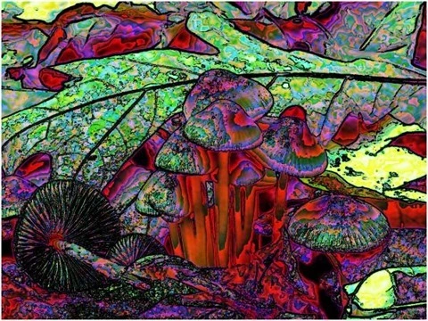
| Colour Values |
Red, Blue |
Filter Size |
9 |
| Edge Tracing |
Black |
Edge Threshold |
55 |
Sample Source Code
This article is accompanied by a sample source code Visual Studio project which is available for download here.

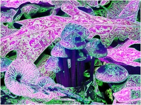
| Colour Values |
Blue |
Filter Size |
9 |
| Edge Tracing |
Double Intensity |
Edge Threshold |
60 |
Using the Sample Application
The sample source code that accompanies this article includes a Windows Forms based sample application. The concepts discussed in this article have been illustrated through the implementation of the sample application.
When executing the sample application, through the user interface several options are made available to the user, described as follows:
- Load/Save Images – Source/input images may be loaded from the local file system through clicking the Load Image button. If desired by the user, resulting output images can be saved to the local file system through clicking the Save Image button.
- Colour Channels – The colour values Red, Green and Blue can be updated or remain unchanged when applying a filter, indicated through the associated Checkboxes.
- Filter Size – The level of filter intensity depends on the size of the filter. Larger filter sizes result in more intense filtering being applied. Smaller filter size result in less intense filtering being applied.
- Colour Shift Type – Colour intensity values can be swapped around through selecting the Colour Shift type: Shift Left and Shift Right.
- Edge Tracing Type – When applying a filter the edges forming part of the original source/input image will be expressed as part of the output image. The method in which image edges are indicated/highlighted will be determined through the type of Edge Tracing specified when applying the filter. Supported types of Edge Tracing include: Black, White, Half Intensity, Double Intensity and Inverted.
- Edge Threshold – Edges forming part of the source/input image are determines through means of image edge detection implementing a threshold value. Lower threshold values result in more emphasized edges expressed within resulting images. Higher threshold values reduce edge emphasis in resulting images.
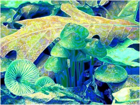
| Colour Values |
Green |
Filter Size |
9 |
| Edge Tracing |
Double Intensity |
Edge Threshold |
60 |
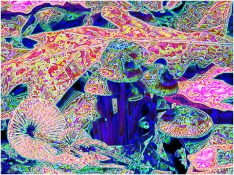
| Colour Values |
Red, Blue |
Filter Size |
9 |
| Edge Tracing |
Double Intensity |
Edge Threshold |
55 |
The following image is a screenshot of the Image Abstract Colour Filter sample application in action:
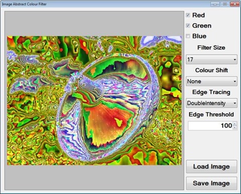
Abstracting Image Colours
The Abstract Colour Filter explored in this article can be considered a non-photo realistic filter. As the title implies, non-photo realistic filters transforms an input image, usually a photograph, producing a result image which visibly lacks the aspects of realism expressed in the input image. In most scenarios the objective of non-photo realistic filters can be described as using photographic images in rendering images having an animated appearance.
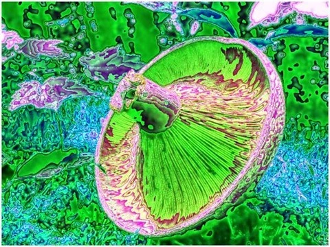
| Colour Values |
Blue |
Filter Size |
11 |
| Edge Tracing |
Double Intensity |
Edge Threshold |
60 |
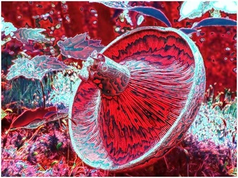
| Colour Values |
Red |
Filter Size |
11 |
| Edge Tracing |
Double Intensity |
Edge Threshold |
60 |
The Abstract Colour Filter can be broken down into two main components: Colour Averaging and Image Edge detection. Through implementing a variety of colour averaging algorithms resulting images express abstract yet uniform colours. Abstract colours result in output images no longer appearing photo realistic, instead output images appear unconventionally augmented/artistic.
Output images express a lesser degree of image definition and detail, when compared to input images. In some scenarios output images might not be easily recognisable. In order to retain some image detail, edge/boundary detail detected from input images will be emphasised in result images.
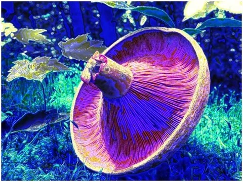
| Colour Values |
Green |
Filter Size |
11 |
| Edge Tracing |
Double Intensity |
Edge Threshold |
60 |
| Colour Values |
Green, Blue |
Filter Size |
11 |
| Edge Tracing |
Double Intensity |
Edge Threshold |
75 |
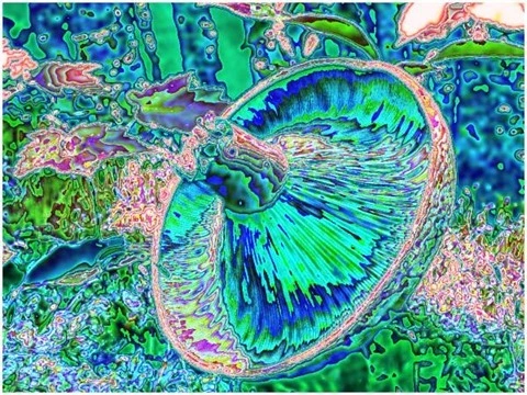
The steps required when applying an Abstract Colour Filter can be described as follows:
- Perform Edge Detection – Using the source/input image perform edge detection, producing a binary image expressing image edges in the foreground/as white.
- Calculate Pixel Neighbourhood Colour Averages – Iterate each pixel forming part of the input image, inspecting the pixel’s neighbouring pixels. Calculate the sum total and average of each colour channel, Red, Green and Blue. The value of the pixel currently being iterated should be set depending to neighbourhood average.
- Trace Edges within Colour Averages – Simultaneously iterate the colour average image and the edge detected image. If the pixel being iterated forms part of an edge, update the corresponding pixel in the average colour image, depending on the specified method of Edge Tracing.
| Colour Values |
Red, Green |
Filter Size |
11 |
| Edge Tracing |
Double Intensity |
Edge Threshold |
75 |
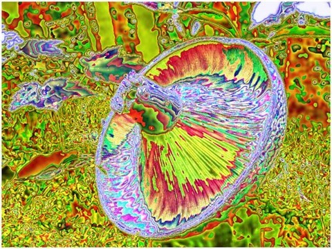
| Colour Values |
Red |
Filter Size |
11 |
| Edge Tracing |
Black |
Edge Threshold |
60 |
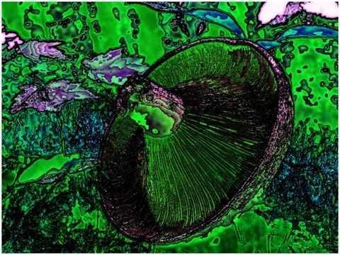
Implementing Pixel Neighbourhood Colour Averaging
In the sample source code neighbourhood colour averaging has been implemented through the definition of the AverageColoursFilter extension method. This method creates a new image using the source image as input. The following code snippet provides the definition:
public static Bitmap AverageColoursFilter(this Bitmap sourceBitmap,
                                          int matrixSize,
                                          bool applyBlue = true,
                                          bool applyGreen = true,
                                          bool applyRed = true,
                                          ColorShiftType shiftType =
                                          ColorShiftType.None)
{
    byte[] pixelBuffer = sourceBitmap.GetByteArray();
    byte[] resultBuffer = new byte[pixelBuffer.Length];


    int calcOffset = 0;
    int byteOffset = 0;
    int blue = 0; int green = 0; int red = 0;
    int filterOffset = (matrixSize - 1) / 2;


    for (int offsetY = filterOffset; offsetY <
        sourceBitmap.Height - filterOffset; offsetY++)
    {
        for (int offsetX = filterOffset; offsetX <
            sourceBitmap.Width - filterOffset; offsetX++)
        {
            byteOffset = offsetY * sourceBitmap.Width*4 +
                         offsetX * 4;


            blue = 0; green = 0; red = 0;


            for (int filterY = -filterOffset;
                filterY <= filterOffset; filterY++)
            {
                for (int filterX = -filterOffset;
                    filterX <= filterOffset; filterX++)
                {
                    calcOffset = byteOffset +
                    (filterX * 4) +
                    (filterY * sourceBitmap.Width * 4);


                    blue += pixelBuffer[calcOffset];
                    green += pixelBuffer[calcOffset + 1];
                    red += pixelBuffer[calcOffset + 2];
                }
            }


            blue = blue / matrixSize;
            green = green / matrixSize;
            red = red / matrixSize;


            if (applyBlue == false )
            { blue = pixelBuffer[byteOffset]; }


            if (applyGreen == false )
            { green = pixelBuffer[byteOffset + 1]; }


            if (applyRed == false )
            { red = pixelBuffer[byteOffset + 2]; }


            if (shiftType == ColorShiftType.None)
            {
                resultBuffer[byteOffset] = (byte)blue;
                resultBuffer[byteOffset + 1] = (byte)green;
                resultBuffer[byteOffset + 2] = (byte)red;
                resultBuffer[byteOffset + 3] = 255;
            }
            else if (shiftType == ColorShiftType.ShiftLeft)
            {
                resultBuffer[byteOffset] = (byte)green;
                resultBuffer[byteOffset + 1] = (byte)red;
                resultBuffer[byteOffset + 2] = (byte)blue;
                resultBuffer[byteOffset + 3] = 255;
            }
            else if (shiftType == ColorShiftType.ShiftRight)
            {
                resultBuffer[byteOffset] = (byte)red;
                resultBuffer[byteOffset + 1] = (byte)blue;
                resultBuffer[byteOffset + 2] = (byte)green;
                resultBuffer[byteOffset + 3] = 255;
            }
        }
    }


    Bitmap resultBitmap = new Bitmap(sourceBitmap.Width,
                                     sourceBitmap.Height);


    BitmapData resultData =
               resultBitmap.LockBits(new Rectangle (0, 0,
               resultBitmap.Width, resultBitmap.Height),
               ImageLockMode.WriteOnly,
               PixelFormat.Format32bppArgb);


    Marshal.Copy(resultBuffer, 0, resultData.Scan0,
                               resultBuffer.Length);


    resultBitmap.UnlockBits(resultData);


    return resultBitmap;
}
| Colour Values |
Green, Blue |
Filter Size |
17 |
| Edge Tracing |
Black |
Edge Threshold |
85 |
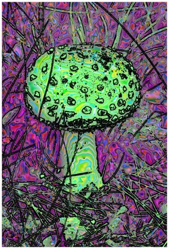
Implementing Gradient Based Edge Detection
When applying an Abstract Colours Filter, one of the required steps involve image edge detection. The sample source code implements Gradient based edge detection through the definition of the GradientBasedEdgeDetectionFilter method. This method has been defined as an extension method targeting the bitmap class. The definition as follows:
public static Bitmap GradientBasedEdgeDetectionFilter(
                        this Bitmap sourceBitmap,
                        byte threshold = 0)
{
    BitmapData sourceData =
               sourceBitmap.LockBits(new Rectangle (0, 0,
               sourceBitmap.Width, sourceBitmap.Height),
               ImageLockMode.ReadOnly,
               PixelFormat.Format32bppArgb);


    byte[] pixelBuffer = new byte[sourceData.Stride * sourceData.Height];
    byte[] resultBuffer = new byte[sourceData.Stride * sourceData.Height];


    Marshal.Copy(sourceData.Scan0, pixelBuffer, 0, pixelBuffer.Length);
    sourceBitmap.UnlockBits(sourceData);


    int sourceOffset = 0, gradientValue = 0;
    bool exceedsThreshold = false;


    for (int offsetY = 1; offsetY <
                          sourceBitmap.Height - 1; offsetY++)
     {
        for (int offsetX = 1; offsetX <
                              sourceBitmap.Width - 1; offsetX++)
         {
            sourceOffset = offsetY * sourceData.Stride +
                           offsetX * 4;
            gradientValue = 0;
            exceedsThreshold = true;


            // Horizontal Gradient
            CheckThreshold(pixelBuffer,
                           sourceOffset - 4,
                           sourceOffset + 4,
                           ref gradientValue, threshold, 2);
            // Vertical Gradient
            exceedsThreshold =
            CheckThreshold(pixelBuffer,
                           sourceOffset - sourceData.Stride,
                           sourceOffset + sourceData.Stride,
                           ref gradientValue, threshold, 2);


            if (exceedsThreshold == false)
             {
                gradientValue = 0;


                // Horizontal Gradient
                exceedsThreshold =
                CheckThreshold(pixelBuffer,
                               sourceOffset - 4,
                               sourceOffset + 4,
                               ref gradientValue, threshold);


                if (exceedsThreshold == false)
                 {
                    gradientValue = 0;


                    // Vertical Gradient
                    exceedsThreshold =
                    CheckThreshold(pixelBuffer,
                                   sourceOffset - sourceData.Stride,
                                   sourceOffset + sourceData.Stride,
                                   ref gradientValue, threshold);


                    if (exceedsThreshold == false)
                     {
                        gradientValue = 0;


                        // Diagonal Gradient : NW-SE
                        CheckThreshold(pixelBuffer,
                                       sourceOffset - 4 - sourceData.Stride,
                                       sourceOffset + 4 + sourceData.Stride,
                                       ref gradientValue, threshold, 2);
                        // Diagonal Gradient : NE-SW
                        exceedsThreshold =
                        CheckThreshold(pixelBuffer,
                                       sourceOffset - sourceData.Stride + 4,
                                       sourceOffset - 4 + sourceData.Stride,
                                       ref gradientValue, threshold, 2);


                        if (exceedsThreshold == false)
                         {
                            gradientValue = 0;


                            // Diagonal Gradient : NW-SE
                            exceedsThreshold =
                            CheckThreshold(pixelBuffer,
                                           sourceOffset - 4 - sourceData.Stride,
                                           sourceOffset + 4 + sourceData.Stride,
                                           ref gradientValue, threshold);


                            if (exceedsThreshold == false)
                             {
                                gradientValue = 0;


                                // Diagonal Gradient : NE-SW
                                exceedsThreshold =
                                CheckThreshold(pixelBuffer,
                                               sourceOffset - sourceData.Stride + 4,
                                               sourceOffset + sourceData.Stride - 4,
                                               ref gradientValue, threshold);
                             }
                         }
                     }
                 }
             }


            resultBuffer[sourceOffset] = (byte)(exceedsThreshold ? 255 : 0);
            resultBuffer[sourceOffset + 1] = resultBuffer[sourceOffset];
            resultBuffer[sourceOffset + 2] = resultBuffer[sourceOffset];
            resultBuffer[sourceOffset + 3] = 255;
         }
     }


    Bitmap resultBitmap = new Bitmap(sourceBitmap.Width, sourceBitmap.Height);


    BitmapData resultData = resultBitmap.LockBits(new Rectangle (0, 0,
                            resultBitmap.Width, resultBitmap.Height),
                            ImageLockMode.WriteOnly, PixelFormat.Format32bppArgb);


    Marshal.Copy(resultBuffer, 0, resultData.Scan0, resultBuffer.Length);
    resultBitmap.UnlockBits(resultData);


    return resultBitmap;
}
| Colour Values |
Red, Green |
Filter Size |
5 |
| Edge Tracing |
Black |
Edge Threshold |
85 |
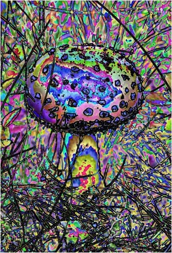
Implementing an Abstract Colour Filter
The AbstractColorsFilter method serves as means of combining an average colour image and an edge detected image. This extension method targets the Bitmap class. The following code snippet details the definition:
public static Bitmap AbstractColorsFilter(this Bitmap sourceBitmap,
                                          int matrixSize,
                                          byte edgeThreshold,
                                          bool applyBlue = true,
                                          bool applyGreen = true,
                                          bool applyRed = true,
                                          EdgeTracingType edgeType =
                                          EdgeTracingType.Black,
                                          ColorShiftType shiftType =
                                          ColorShiftType.None)
{
    Bitmap edgeBitmap =
    sourceBitmap.GradientBasedEdgeDetectionFilter(edgeThreshold);


    Bitmap colorBitmap =
    sourceBitmap.AverageColoursFilter(matrixSize,
                 applyBlue, applyGreen, applyRed, shiftType);


    byte[] edgeBuffer = edgeBitmap.GetByteArray();
    byte[] colorBuffer = colorBitmap.GetByteArray();
    byte[] resultBuffer = colorBitmap.GetByteArray();


    for (int k = 0; k + 4 < edgeBuffer.Length; k += 4)
    {
        if (edgeBuffer[k] == 255)
        {
            switch (edgeType)
            {
                case EdgeTracingType.Black:
                    resultBuffer[k] = 0;
                    resultBuffer[k+1] = 0;
                    resultBuffer[k+2] = 0;
                    break;
                case EdgeTracingType.White:
                    resultBuffer[k] = 255;
                    resultBuffer[k+1] = 255;
                    resultBuffer[k+2] = 255;
                    break;
                case EdgeTracingType.HalfIntensity:
                    resultBuffer[k] = ClipByte(resultBuffer[k] * 0.5);
                    resultBuffer[k + 1] = ClipByte(resultBuffer[k + 1] * 0.5);
                    resultBuffer[k + 2] = ClipByte(resultBuffer[k + 2] * 0.5);
                    break;
                case EdgeTracingType.DoubleIntensity:
                    resultBuffer[k] = ClipByte(resultBuffer[k] * 2);
                    resultBuffer[k + 1] = ClipByte(resultBuffer[k + 1] * 2);
                    resultBuffer[k + 2] = ClipByte(resultBuffer[k + 2] * 2);
                    break;
                case EdgeTracingType.ColorInversion:
                    resultBuffer[k] = ClipByte(255 - resultBuffer[k]);
                    resultBuffer[k+1] = ClipByte(255 - resultBuffer[k+1]);
                    resultBuffer[k+2] = ClipByte(255 - resultBuffer[k+2]);
                    break;
            }
        }
    }


    Bitmap resultBitmap = new Bitmap (sourceBitmap.Width,
                                    sourceBitmap.Height);


    BitmapData resultData =
               resultBitmap.LockBits(new Rectangle (0, 0,
               resultBitmap.Width, resultBitmap.Height),
               ImageLockMode.WriteOnly,
               PixelFormat.Format32bppArgb);


    Marshal.Copy(resultBuffer, 0, resultData.Scan0,
                               resultBuffer.Length);


    resultBitmap.UnlockBits(resultData);


    return resultBitmap;
}
| Colour Values |
Red, Green |
Filter Size |
17 |
| Edge Tracing |
Double Intensity |
Edge Threshold |
85 |
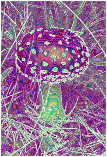
Sample Images
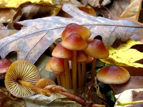
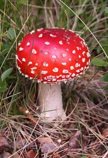
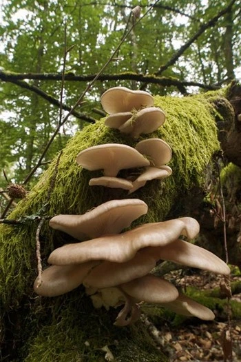
This article features a number of sample images. All featured images have been licensed allowing for reproduction. The following images feature as sample images:

Additional Filter Result Images
The following series of images represent additional filter results.
| Colour Values |
Red |
Filter Size |
9 |
| Edge Tracing |
Double Intensity |
Edge Threshold |
60 |
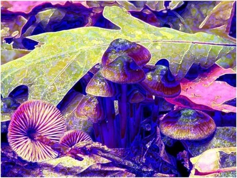
| Colour Values |
Green, Blue |
Filter Size |
9 |
| Edge Tracing |
Double Intensity |
Edge Threshold |
60 |
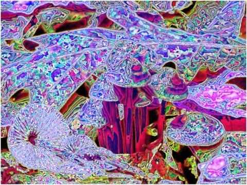
| Colour Values |
Green, Blue |
Filter Size |
9 |
| Edge Tracing |
Black |
Edge Threshold |
60 |
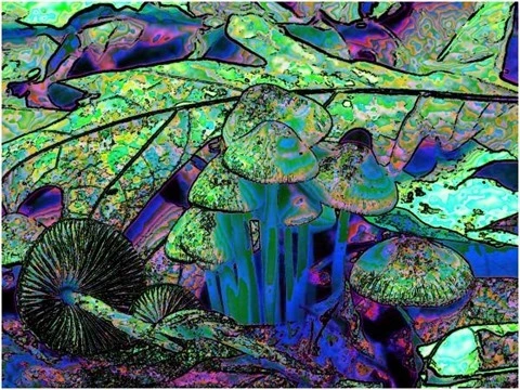
| Colour Values |
Red, Green, Blue |
Filter Size |
9 |
| Edge Tracing |
Double Intensity |
Edge Threshold |
55 |
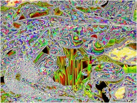
| Colour Values |
Red, Green, Blue |
Filter Size |
11 |
| Edge Tracing |
Black |
Edge Threshold |
75 |
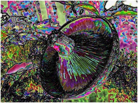
| Colour Values |
Red, Blue |
Filter Size |
11 |
| Edge Tracing |
Double Intensity |
Edge Threshold |
75 |
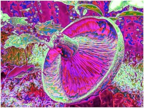
| Colour Values |
Green |
Filter Size |
17 |
| Edge Tracing |
Black |
Edge Threshold |
85 |
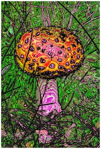
| Colour Values |
Red |
Filter Size |
17 |
| Edge Tracing |
Black |
Edge Threshold |
85 |
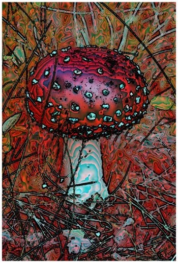
| Colour Values |
Red, Green, Blue |
Filter Size |
5 |
| Edge Tracing |
Half Edge |
Edge Threshold |
85 |
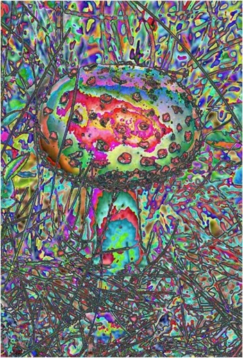
| Colour Values |
Blue |
Filter Size |
5 |
| Edge Tracing |
Double Intensity |
Edge Threshold |
75 |
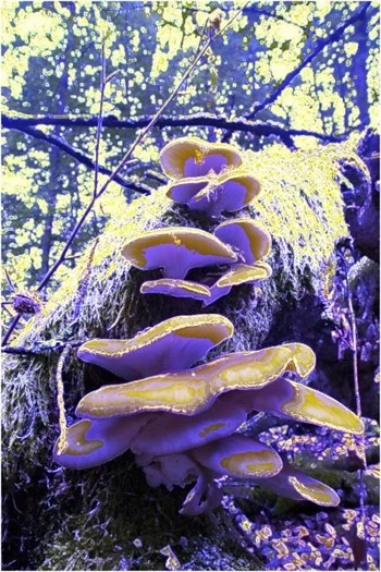
| Colour Values |
Green |
Filter Size |
5 |
| Edge Tracing |
Double Intensity |
Edge Threshold |
75 |

| Colour Values |
Red |
Filter Size |
5 |
| Edge Tracing |
Double Intensity |
Edge Threshold |
75 |
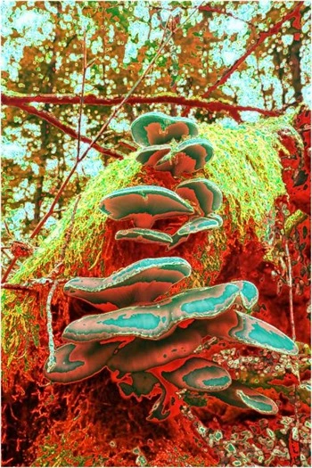
| Colour Values |
Red, Green, Blue |
Filter Size |
5 |
| Edge Tracing |
Black |
Edge Threshold |
75 |
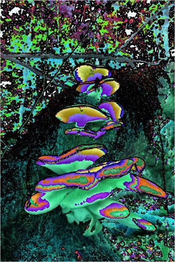
| Colour Values |
Red, Green, Blue |
Filter Size |
9 |
| Edge Tracing |
Black |
Edge Threshold |
55 |
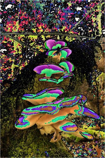
| Colour Values |
Red, Green, Blue |
Filter Size |
3 |
| Edge Tracing |
Black |
Edge Threshold |
75 |
Related Articles and Feedback
Feedback and questions are always encouraged. If you know of an alternative implementation or have ideas on a more efficient implementation please share in the comments section.
Dewald Esterhuizen
I’ve published a number of articles related to imaging and images of which you can find URL links here:


