Posts Tagged 'System.Drawing'

C# How to: Swapping Bitmap ARGB Colour Channels

Article Purpose

The intention of is to explain and illustrate the various possible combinations that can be implemented when swapping the underlying colour channels related to a  image. The concepts explained can easily be replicated by making use of the included sample application.

Sample source code

is accompanied by a sample source code Visual Studio project which is available for download here.

Using the sample Application

The sample application associated with allows the user to select a source image, apply a colour shifting option. The user is provided  with the option to save to disk the resulting new . The below is a screenshot of the Bitmap ARGB Swapping application in action:

SampleAppScreenshot

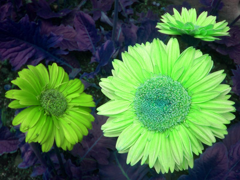
The scenario illustrated above shows an of flowers being transformed by swapping the underlying colour channels. In this case the ShiftLeft algorithm had been applied. The original is licenced under the , the original image can be downloaded from Wikipedia.

Types of Colour Swapping

The sample source code defines the type ColorSwapType, which represents the possible combinations of colour channel swapping that can be applied to a . The source code extract below provides the definition of the ColorSwapType :

public enum ColorSwapType
{
    ShiftRight,
    ShiftLeft,
    SwapBlueAndRed,
    SwapBlueAndGreen,
    SwapRedAndGreen,
}

When directly manipulating a object’s pixel values an important detail should be noted: Bitmap colour channels in memory are represented in the order Blue, Green, Red and Alpha despite being commonly referred to by abbreviation ARGB!

The following list describes each colour swapping type’s outcome:

  • ShiftRight: Starting at Blue, each colour’s value is set to the colour channel to the right. The value of Blue is applied to Red, Red’s original value applied to Green, Green’s original value applied to Blue.
  • ShiftLeft: Starting at Blue, each colour’s value is set to the colour channel to the left. The value of Blue is applied to Green, Green’s original value applied to Red, Red’s original value applied to Blue.
  • SwapBlueAndRed: The value of the Blue channel is applied to the Red channel and the original value of the Red channel is then applied to the Blue channel. The value of the Green channel remains unchanged.
  • SwapBlueAndGreen: The value of the Blue channel is applied to the Green channel and the original value of the Green channel is then applied to the Blue channel. The value of the Red  channel remains unchanged.
  • SwapRedAndGreen: The value of the Red channel is applied to the Green channel and the original value of the Green channel is then applied to the Red channel. The value of the Blue channel remains unchanged.

The Colour Swap Filter

The sample source code defines the ColorSwapFilter class. This class provides several member properties, which in combination represent the options involved in applying a colour swap filter. The source code snippet below provides the definition of the ColorSwapFilter type:

public class ColorSwapFilter
{
   private ColorSwapType swapType = ColorSwapType.ShiftRight;
   public ColorSwapType SwapType
   {
        get{ return swapType;}
        set{ swapType = value;}
   }

private bool swapHalfColorValues = false; public bool SwapHalfColorValues { get{ return swapHalfColorValues;} set{ swapHalfColorValues = value;} }
private bool invertColorsWhenSwapping = false; public bool InvertColorsWhenSwapping { get{ return invertColorsWhenSwapping;} set{ invertColorsWhenSwapping = value;} }
public enum ColorSwapType { ShiftRight, ShiftLeft, SwapBlueAndRed, SwapBlueAndGreen, SwapRedAndGreen, } }

The member properties defined by the ColorSwapFilter class:

  • Implementing the ColorSwapType discussed earlier, the SwapType member property defines the type of colour channel swapping to apply.
  • Before swapping colour channel values, colour values can be inverted depending on whether InvertColorsWhenSwapping equates to true.
  • In order to reduce the intensity of the resulting image, the SwapHalfColorValues property should be set to true. The end result being destination colour channels are set to 50% of relevant source colour channel values.

Applying the Colour Swap Filter

The sample source code accompanying defines the SwapColorsCopy method, an targeting class. When invoking the SwapColorsCopy extension method, the calling code is required to specify an input and an instance of the ColorSwapFilter class. By virtue of being an the input/source will be specified by the object instance invoking the SwapColorsCopy method.

The source code listing below provides the definition of the SwapColorsCopy .

public static Bitmap SwapColorsCopy(this Bitmap originalImage, ColorSwapFilter swapFilterData)
{
    BitmapData sourceData = originalImage.LockBits
                            (new Rectangle(0, 0, originalImage.Width, originalImage.Height),
                            ImageLockMode.ReadOnly, PixelFormat.Format32bppArgb);

byte[] resultBuffer = new byte[sourceData.Stride * sourceData.Height]; Marshal.Copy(sourceData.Scan0, resultBuffer, 0, resultBuffer.Length); originalImage.UnlockBits(sourceData);
byte sourceBlue = 0, resultBlue = 0, sourceGreen = 0, resultGreen = 0, sourceRed = 0, resultRed = 0; byte byte2 = 2, maxValue = 255;
for (int k = 0; k < resultBuffer.Length; k += 4) { sourceBlue = resultBuffer[k]; sourceGreen = resultBuffer[k + 1]; sourceRed = resultBuffer[k + 2];
if (swapFilterData.InvertColorsWhenSwapping == true) { sourceBlue = (byte)(maxValue - sourceBlue); sourceGreen = (byte)(maxValue - sourceGreen); sourceRed = (byte)(maxValue - sourceRed); }
if (swapFilterData.SwapHalfColorValues == true) { sourceBlue = (byte)(sourceBlue / byte2); sourceGreen = (byte)(sourceGreen / byte2); sourceRed = (byte)(sourceRed / byte2); }
switch (swapFilterData.SwapType) { case ColorSwapFilter.ColorSwapType.ShiftRight: { resultBlue = sourceGreen; resultRed = sourceBlue; resultGreen = sourceRed; break; } case ColorSwapFilter.ColorSwapType.ShiftLeft: { resultBlue = sourceRed; resultRed = sourceGreen; resultGreen = sourceBlue; break; } case ColorSwapFilter.ColorSwapType.SwapBlueAndRed: { resultBlue = sourceRed; resultRed = sourceBlue; break; } case ColorSwapFilter.ColorSwapType.SwapBlueAndGreen: { resultBlue = sourceGreen; resultGreen = sourceBlue; break; } case ColorSwapFilter.ColorSwapType.SwapRedAndGreen: { resultRed = sourceGreen; resultGreen = sourceGreen; break; } }
resultBuffer[k] = resultBlue; resultBuffer[k + 1] = resultGreen; resultBuffer[k + 2] = resultRed; }
Bitmap resultBitmap = new Bitmap(originalImage.Width, originalImage.Height, PixelFormat.Format32bppArgb); BitmapData resultData = resultBitmap.LockBits (new Rectangle(0, 0, resultBitmap.Width, resultBitmap.Height), ImageLockMode.WriteOnly, PixelFormat.Format32bppArgb);
Marshal.Copy(resultBuffer, 0, resultData.Scan0, resultBuffer.Length); resultBitmap.UnlockBits(resultData);
return resultBitmap; }

Due to the architecture and implementation of the .net when manipulating a object’s underlying colour values we need to ensure locking the relevant data buffer in memory. When invoking the class’ method the calling code prevents the from shifting and updating memory references. Once a ’s underlying pixel buffer has been locked in memory the source code creates a data buffer of type byte array and then copies the ’s underlying pixel buffer data.

BitmapData sourceData = originalImage.LockBits
                        (new Rectangle(0, 0, originalImage.Width, originalImage.Height),
                        ImageLockMode.ReadOnly, PixelFormat.Format32bppArgb);

byte[] resultBuffer = new byte[sourceData.Stride * sourceData.Height]; Marshal.Copy(sourceData.Scan0, resultBuffer, 0, resultBuffer.Length); originalImage.UnlockBits(sourceData);

The sample source code next iterates the pixel buffer array. Notice how the for loop increments by 4 with each loop. Every four elements of the data buffer in combination represents one pixel, each colour channel expressed as a value ranging from 0 to 255 inclusive.

for (int k = 0; k < resultBuffer.Length; k += 4)

If required each colour channel will first be assigned to a value equating to its inverse value by subtracting from 255.

if (swapFilterData.InvertColorsWhenSwapping == true)
{
     sourceBlue = (byte)(maxValue - sourceBlue);
     sourceGreen = (byte)(maxValue - sourceGreen);
     sourceRed = (byte)(maxValue - sourceRed);
}

When the supplied ColorSwapFilter object method parameter defines SwapHalfColorValues as true the source colour value will be divided by 2.

if (swapFilterData.SwapHalfColorValues == true)
{
     sourceBlue = (byte)(sourceBlue / byte2);
     sourceGreen = (byte)(sourceGreen / byte2);
     sourceRed = (byte)(sourceRed / byte2);
}
 

The next section implements a case statement, each option implementing the required colour channel swap algorithm. The last step expressed as part of the for loop results in assigning newly manipulated values to the data buffer.

The SwapColorsCopy extension method can be described as being immutable in the sense that the input value remains unchanged, instead manipulating and returning a copy of the input data. Following the data buffer iteration the sample source creates a new instance of the class and locks it into memory by invoking the method. By implementing the method the source code copies the data buffer to the underlying buffer associated with the newly created object.

 Bitmap resultBitmap = new Bitmap(originalImage.Width, originalImage.Height, 
                                     PixelFormat.Format32bppArgb);
 
BitmapData resultData = resultBitmap.LockBits (new Rectangle(0, 0, resultBitmap.Width, resultBitmap.Height), ImageLockMode.WriteOnly, PixelFormat.Format32bppArgb);
Marshal.Copy(resultBuffer, 0, resultData.Scan0, resultBuffer.Length); resultBitmap.UnlockBits(resultData);
return resultBitmap;

The implementation: a

The sample source code accompanying defines a , the intention of which being to illustrate a test implementation. The following series of images were created using the sample application:

The source/input image is licenced under the , the original image can be downloaded from Wikipedia.

The Original Image

800px-HK_Sheung_Wan_Hollywood_Road_Park_Flowers_in_Purple

The ShiftLeft Colour Swapping algorithm:

ShiftLeft

Inverted:

ShiftLeft_inverted

The ShiftRight Colour Swapping algorithm:

ShiftRight

Inverted:

ShiftRight_inverted

The SwapBlueAndGreen Colour Swapping algorithm:

SwapBlueAndGreen

Inverted:

SwapBlueAndGreen_inverted

The SwapBlueAndRed Colour Swapping algorithm:

SwapBlueAndRed

Inverted:

SwapBlueAndRed_inverted

The SwapRedAndGreen Colour Swapping algorithm:

SwapRedAndGreen

Inverted:

SwapRedAndGreen_inverted

Related Articles and Feedback

Feedback and questions are always encouraged. If you know of an alternative implementation or have ideas on a more efficient implementation please share in the comments section.

I’ve published a number of articles related to imaging and images of which you can find URL links here:

C# How to: Generating Icons from Images

Article Purpose

This illustrates the process of generating files (*.ico) from user specified input . The accompanying Sample Source Code implements a , allowing for easily testing the generation process.

Sample source code

This is accompanied by a sample source code Visual Studio project which is available for download .

Using the sample Application

The Sample Application can be used to test/implement the concepts described in this . The user interface enables the user to browse and select an file from the file system, which loads as a scaled preview. In addition, the user can select an size from a list of standard dimensions: 16×16, 24×24, 32×32, 48×48, 64×64, 96×96 and 128×128 pixels. When a user clicks on the “Save Icon” button the sample application generates an in memory based on the specified size converting and scaling the provided input . If an was successfully generated, the in-memory representation will be saved to the file system, based on the filename and file path specified by the user.

The image below is screenshot of the Image to Icon Generator application in action:

Image To Icon Generator

The source features Bellis perennis also known as the common European Daisy (see Wikipedia). The file is licensed under the Creative Commons Attribution-Share Alike 2.5 Generic license. The original can be downloaded from .

The resulting file generated by the sample application:

Generating Icons from Images

Scaling and Aspect Ratio

conform to a set of standard dimensions, all of which equate to a square due to the width and height values being equal. A potential issue exists in that the specified source might not have exact square dimensions. In other words, the width and height values of specified source might differ. The solution lies in creating a square based on the specified source . Consider the concept of a square canvas onto which is drawn the source whilst maintaining its aspect ratio, implementing center alignment from the horizontal and vertical aspect. Listed below is the implementation of an defined as CopyToSquareCanvas, targeting the class.

public static Bitmap CopyToSquareCanvas(this Bitmap sourceBitmap, Color canvasBackground)
{
    int maxSide = sourceBitmap.Width > sourceBitmap.Height ? sourceBitmap.Width : sourceBitmap.Height;

Bitmap bitmapResult = new Bitmap(maxSide, maxSide, PixelFormat.Format32bppArgb);
using (Graphics graphicsResult = Graphics.FromImage(bitmapResult)) { graphicsResult.Clear(canvasBackground);
int xOffset = (sourceBitmap.Width - maxSide) / 2; int yOffset = (sourceBitmap.Height - maxSide) / 2;
graphicsResult.DrawImage(sourceBitmap, new Point(xOffset, xOffset)); }
return bitmapResult; }

The size of the resulting is determined by the source ’s longest side, either width or height. To ensure middle alignment both vertically and horizontally the source is drawn at an offset, determined by the additional buffer area added by the canvas.

Generating the Icon

Once we have created an conforming to exact square dimensions the next step would be to scale said to the desired size. A convenient method of quickly scaling source to icon dimensions comes in the form of creating .

The sample source code defines the enumeration IconSizeDimensions, which serves to provide a developer friendly reference coupled with actual dimension values by means of specifying explicit enumeration values. Consider the following code snippet:

public enum IconSizeDimensions
{
    IconSize16x16Pixels = 16,
    IconSize24x24Pixels = 24,
    IconSize32x32Pixels = 32,
    IconSize48x48Pixels = 48,
    IconSize64x64Pixels = 64,
    IconSize96x96Pixels = 96,
    IconSize128x128Pixels = 128
}

The crux of this and sample source code can considered to be the definition of the CreateIcon , which targets the class. The definition is as follows:

public static Icon CreateIcon(this Bitmap sourceBitmap, IconSizeDimensions iconSize)
{
    Bitmap squareCanvas = sourceBitmap.CopyToSquareCanvas(Color.Transparent);
    squareCanvas = (Bitmap)squareCanvas.GetThumbnailImage((int)iconSize, (int)iconSize, null, new IntPtr());

Icon iconResult = Icon.FromHandle(squareCanvas.GetHicon());
return iconResult; }

As discussed the first step is to ensure that the source conforms to square dimensions, implemented here by invoking the CopyToSquareCanvas . Next the source code implements scaling by creating a of which the size is based on the specified IconSizeDimensions value. The method returns a handle to an in the form of an , which serves as a parameter to the static method, which returns an instance of the class.

The Implementation

When the user clicks the “Save” button the Sample Application will present the user with a file save dialog. After the user specifies a file name and file path the Sample Application creates a reference of the source by casting the picturebox’s property to type .

private void btnSaveIcon_Click(object sender, EventArgs e)
{
    if (picSource.Image != null)
    {
        SaveFileDialog sfd = new SaveFileDialog();
        sfd.Title = "Specify a file name and file path";
        sfd.Filter = "Icon Files(*.ico)|*.ico"; 
if (sfd.ShowDialog() == System.Windows.Forms.DialogResult.OK) { System.Drawing.Icon tempIcon = ((Bitmap)picSource.Image).CreateIcon( (IconSizeDimensions)cmbIconSize.SelectedItem);
using (StreamWriter streamWriter = new StreamWriter(sfd.FileName, false)) { tempIcon.Save(streamWriter.BaseStream);
streamWriter.Flush(); streamWriter.Close(); } } } }

When the CreateIcon is invoked, the dimensions selected through the user interface will be passed as a parameter. The last step performed involves persisting the in-memory data to the file system.

C# How to: Bitmap Colour Substitution implementing thresholds

Article Purpose

This article is aimed at detailing how to implement the process of substituting the colour values that form part of a image. Colour substitution is implemented by means of a threshold value. By implementing a threshold a range of similar colours can be substituted.

Sample source code

This article is accompanied by a sample source code Visual Studio project which is available for download here.

Using the sample Application

The provided sample source code builds a Windows Forms application which can be used to test/implement the concepts described in this article. The sample application enables the user to load an file from the file system, the user can then specify the colour to replace, the replacement colour and the threshold to apply. The following image is a screenshot of the sample application in action.

BitmapColourSubstitution_Scaled

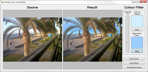
The scenario detailed in the above screenshot shows the sample application being used to create an where the sky has more of a bluish hue when compared to the original .

Notice how replacement colour does not simply appear as a solid colour applied throughout. The replacement colour gets implemented matching the intensity of the colour being substituted.

The colour filter options:

FilterOptions

The colour to replace was taken from the original , the replacement colour is specified through a colour picker dialog. When a user clicks on either displayed, the colour of the pixel clicked on sets the value of the replacement colour. By adjusting the threshold value the user can specify how wide or narrow the range of colours to replace should be. The higher the threshold value, the wider the range of colours that will be replaced.

The resulting image can be saved by clicking the “Save Result” button. In order to apply another colour substitution on the resulting image click the button labelled “Set Result as Source”.

Colour Substitution Filter Data

The sample source code provides the definition for the ColorSubstitutionFilter class. The purpose of this class is to contain data required when applying colour substitution. The ColorSubstitutionFilter class is defined as follows:

public class ColorSubstitutionFilter
{
    private int thresholdValue = 10;
    public int ThresholdValue
    {
        get { return thresholdValue; }
        set { thresholdValue = value; }
    }

private Color sourceColor = Color.White; public Color SourceColor { get { return sourceColor; } set { sourceColor = value; } }
private Color newColor = Color.White; public Color NewColor { get { return newColor; } set { newColor = value; } } }

To implement a colour substitution filter we first have to create an object instance of type ColorSubstitutionFilter. A colour substitution requires specifying a SourceColor, which is the colour to replace/substitute and a NewColour, which defines the colour that will replace the SourceColour. Also required is a ThresholdValue, which determines a range of colours based on the SourceColor.

Colour Substitution implemented as an Extension method

The sample source code defines the ColorSubstitution extension method which targets the class. Invoking the ColorSubstitution requires passing a parameter of type ColorSubstitutionFilter, which defines how colour substitution is to be implemented. The following code snippet contains the definition of the ColorSubstitution method.

public static Bitmap ColorSubstitution(this Bitmap sourceBitmap, ColorSubstitutionFilter filterData)
{
    Bitmap resultBitmap = new Bitmap(sourceBitmap.Width, sourceBitmap.Height, PixelFormat.Format32bppArgb);

BitmapData sourceData = sourceBitmap.LockBits(new Rectangle(0, 0, sourceBitmap.Width, sourceBitmap.Height), ImageLockMode.ReadOnly, PixelFormat.Format32bppArgb); BitmapData resultData = resultBitmap.LockBits(new Rectangle(0, 0, resultBitmap.Width, resultBitmap.Height), ImageLockMode.WriteOnly, PixelFormat.Format32bppArgb);
byte[] resultBuffer = new byte[resultData.Stride * resultData.Height]; Marshal.Copy(sourceData.Scan0, resultBuffer, 0, resultBuffer.Length);
sourceBitmap.UnlockBits(sourceData);
byte sourceRed = 0, sourceGreen = 0, sourceBlue = 0, sourceAlpha = 0; int resultRed = 0, resultGreen = 0, resultBlue = 0;
byte newRedValue = filterData.NewColor.R; byte newGreenValue = filterData.NewColor.G; byte newBlueValue = filterData.NewColor.B;
byte redFilter = filterData.SourceColor.R; byte greenFilter = filterData.SourceColor.G; byte blueFilter = filterData.SourceColor.B;
byte minValue = 0; byte maxValue = 255;
for (int k = 0; k < resultBuffer.Length; k += 4) { sourceAlpha = resultBuffer[k + 3];
if (sourceAlpha != 0) { sourceBlue = resultBuffer[k]; sourceGreen = resultBuffer[k + 1]; sourceRed = resultBuffer[k + 2];
if ((sourceBlue < blueFilter + filterData.ThresholdValue && sourceBlue > blueFilter - filterData.ThresholdValue) &&
(sourceGreen < greenFilter + filterData.ThresholdValue && sourceGreen > greenFilter - filterData.ThresholdValue) &&
(sourceRed < redFilter + filterData.ThresholdValue && sourceRed > redFilter - filterData.ThresholdValue)) { resultBlue = blueFilter - sourceBlue + newBlueValue;
if (resultBlue > maxValue) { resultBlue = maxValue;} else if (resultBlue < minValue) { resultBlue = minValue;}
resultGreen = greenFilter - sourceGreen + newGreenValue;
if (resultGreen > maxValue) { resultGreen = maxValue;} else if (resultGreen < minValue) { resultGreen = minValue;}
resultRed = redFilter - sourceRed + newRedValue;
if (resultRed > maxValue) { resultRed = maxValue;} else if (resultRed < minValue) { resultRed = minValue;}
resultBuffer[k] = (byte)resultBlue; resultBuffer[k + 1] = (byte)resultGreen; resultBuffer[k + 2] = (byte)resultRed; resultBuffer[k + 3] = sourceAlpha; } } }
Marshal.Copy(resultBuffer, 0, resultData.Scan0, resultBuffer.Length); resultBitmap.UnlockBits(resultData);
return resultBitmap; }

The ColorSubstitution method can be labelled as due to its implementation. Being implies that the source/input data will not be modified, instead a new instance will be created reflecting the source data as modified by the operations performed in the particular method.

The first statement defined in the ColorSubstitution method body instantiates an instance of a new , matching the size dimensions of the source object. Next the method invokes the method on the source and result instances. When invoking the underlying data representing a will be locked in memory. Being locked in memory can also be described as signalling/preventing the Garbage Collector to not move around in memory the data being locked. Invoking results in the Garbage Collector functioning as per normal, moving data in memory and updating the relevant memory references when required.

The source code continues by copying all the representing the source to an array of bytes that represents the resulting . At this stage the source and result s are exactly identical and as yet unmodified. In order to determine which pixels based on colour should be modified the source code iterates through the byte array associated with the result .

Notice how the for loop increments by 4 with each loop. The underlying data represents a 32 Bits per pixel Argb , which equates to 8 bits/1 representing an individual colour component, either Alpha, Red, Green or Blue. Defining the for loop to increment by 4 results in each loop iterating 4 or 32 bits, in essence 1 pixel.

Within the for loop we determine if the colour expressed by the current pixel adjusted by the threshold value forms part of the colour range that should be updated. It is important to remember that an individual colour component is a byte value and can only be set to a value between 0 and 255 inclusive.

The Implementation

The ColorSubstitution method is implemented by the sample source code  through a Windows Forms application. The ColorSubstitution method requires that the source specified must be  formatted as a 32 Bpp Argb . When the user loads a source image from the file system the sample application attempts to convert the selected file by invoking the Format32bppArgbCopy which targets the class. The definition is as follows:

public static Bitmap Format32bppArgbCopy(this Bitmap sourceBitmap)
{
    Bitmap copyBitmap = new Bitmap(sourceBitmap.Width, sourceBitmap.Height, PixelFormat.Format32bppArgb);

using (Graphics graphicsObject = Graphics.FromImage(copyBitmap)) { graphicsObject.CompositingQuality = System.Drawing.Drawing2D.CompositingQuality.HighQuality; graphicsObject.InterpolationMode = System.Drawing.Drawing2D.InterpolationMode.HighQualityBicubic; graphicsObject.PixelOffsetMode = System.Drawing.Drawing2D.PixelOffsetMode.HighQuality; graphicsObject.SmoothingMode = System.Drawing.Drawing2D.SmoothingMode.HighQuality;
graphicsObject.DrawImage(sourceBitmap, new Rectangle(0, 0, sourceBitmap.Width, sourceBitmap.Height), new Rectangle(0, 0, sourceBitmap.Width, sourceBitmap.Height), GraphicsUnit.Pixel); }
return copyBitmap; }

Colour Substitution Examples

The following section illustrates a few examples of colour substitution result . The source image features Bellis perennis also known as the common European Daisy (see Wikipedia). The image file is licensed under the Creative Commons Attribution-Share Alike 2.5 Generic license. The original image can be downloaded here. The following image is a scaled down version of the original:

Bellis_perennis_white_(aka)_scaled

Light Blue Colour Substitution

Colour Component Source Colour Substitute Colour
Red   255   121
Green   223   188
Blue   224   255

Daisy_light_blue

Medium Blue Colour Substitution

Colour Component Source Colour Substitute Colour
Red   255   34
Green   223   34
Blue   224   255

Daisy_medium_blue

Medium Green Colour Substitution

Colour Component Source Colour Substitute Colour
Red   255   0
Green   223   128
Blue   224   0

Daisy_medium_green

Purple Colour Substitution

Colour Component Source Colour Substitute Colour
Red   255   128
Green   223   0
Blue   224   255

Daisy_purple

Related Articles and Feedback

Feedback and questions are always encouraged. If you know of an alternative implementation or have ideas on a more efficient implementation please share in the comments section.

I’ve published a number of articles related to imaging and images of which you can find URL links here:

C# How to: Image filtering implemented using a ColorMatrix

Article purpose

This is based around creating basic filters. The different types of filters discussed are: Grayscale, Transparency, Image Negative and Sepia tone. All filters are implemented as targeting the Image class, as well as the Bitmap class as the result of inheritance and upcasting.

Note: This is a follow up to . The previously published related article implements filtering by performing calculations and updating pixel colour component values namely Alpha, Red, Green and Blue. This achieves the same filtering through implementing various transformations, in essence providing an alternative solution. For the sake of convenience I have included the pixel manipulation in addition to the detailed by this article.

Sample source code

This is accompanied by a sample source code Visual Studio project which is available for download .

Implementing a ColorMatrix

From :

Defines a 5 x 5 matrix that contains the coordinates for the RGBAW space. Several methods of the ImageAttributes class adjust image colors by using a color matrix.

The matrix coefficients constitute a 5 x 5 linear transformation that is used for transforming ARGB homogeneous values. For example, an ARGB vector is represented as red, green, blue, alpha and w, where w is always 1.

When implementing a translation using the class values specified are added to one or more of the four colour components. A value that is to be added may only range from 0 to 1 inclusive. Note that adding a negative value results in subtracting values. A good article that illustrates implementing a can be found on MSDN: How to: Translate Image Colors.

The following code snippet provides the implementation of the ApplyColorMatrix method.

private static Bitmap ApplyColorMatrix(Image sourceImage, ColorMatrix colorMatrix)
{
    Bitmap bmp32BppSource = GetArgbCopy(sourceImage);
    Bitmap bmp32BppDest = new Bitmap(bmp32BppSource.Width, bmp32BppSource.Height, PixelFormat.Format32bppArgb);

using (Graphics graphics = Graphics.FromImage(bmp32BppDest)) { ImageAttributes bmpAttributes = new ImageAttributes(); bmpAttributes.SetColorMatrix(colorMatrix); graphics.DrawImage(bmp32BppSource, new Rectangle(0, 0, bmp32BppSource.Width, bmp32BppSource.Height), 0, 0, bmp32BppSource.Width, bmp32BppSource.Height, GraphicsUnit.Pixel, bmpAttributes);
}
bmp32BppSource.Dispose();
return bmp32BppDest; }

The ApplyColorMatrix method signature defines a parameter of type and a second parameter of type . This method is intended to apply the specified upon the parameter specified.

The source is firstly copied in order to ensure that the that is to be transformed is defined with a pixel format of 32 bits per pixel, consisting of the colour components Alpha, Red, Green and Blue. Next we create a blank memory defined to reflect the same size dimensions as the original source . A can be implemented by means of applying an when invoking the defined by the class.

Creating an ARGB copy

The source code snippet listed below converts source images into 32Bit ARGB formatted :

private static Bitmap GetArgbCopy(Image sourceImage)
{
    Bitmap bmpNew = new Bitmap(sourceImage.Width, sourceImage.Height, PixelFormat.Format32bppArgb);

using(Graphics graphics = Graphics.FromImage(bmpNew)) { graphics.DrawImage(sourceImage, new Rectangle (0, 0, bmpNew.Width, bmpNew.Height), new Rectangle (0, 0, bmpNew.Width, bmpNew.Height), GraphicsUnit.Pixel); graphics.Flush(); }
return bmpNew; }

The GetArgbCopy method creates a blank memory Bitmap having the same size dimensions as the source image. The newly created Bitmap is explicitly specified to conform to a 32Bit ARGB format. By making use of a Graphics object of which the context is bound to the new Bitmap instance the source code draws the original image to the new Bitmap.

The Transparency Filter

The transparency filter is intended to create a copy of an , increase the copy’s level of transparency and return the modified copy to the calling code. Listed below is source code which defines the DrawWithTransparency extension method.

public static Bitmap DrawWithTransparency(this Image sourceImage)
{
    ColorMatrix colorMatrix = new ColorMatrix(new float[][]
                        {
                            new float[]{1, 0, 0, 0, 0},
                            new float[]{0, 1, 0, 0, 0},
                            new float[]{0, 0, 1, 0, 0},
                            new float[]{0, 0, 0, 0.3f, 0},
                            new float[]{0, 0, 0, 0, 1}
                        });

return ApplyColorMatrix(sourceImage, colorMatrix); }

Due to the ApplyColorMatrix method defined earlier implementing an filter simply consists of defining the filter algorithm in the form of a and then invoking ApplyColorMatrix.

The is defined to apply no change to the Red, Green and Blue components whilst reducing the Alpha component by 70%.

Image Filters Transparency ColorMatrix

The Grayscale Filter

All of the filter illustrated in this are implemented in a fashion similar to the DrawWithTransparency method. The DrawAsGrayscale is implemented as follows:

public static Bitmap DrawAsGrayscale(this Image sourceImage)
{
    ColorMatrix colorMatrix = new ColorMatrix(new float[][]
                        {
                            new float[]{.3f, .3f, .3f, 0, 0},
                            new float[]{.59f, .59f, .59f, 0, 0},
                            new float[]{.11f, .11f, .11f, 0, 0},
                            new float[]{0, 0, 0, 1, 0},
                            new float[]{0, 0, 0, 0, 1}
                        });

return ApplyColorMatrix(sourceImage, colorMatrix); }

The grayscale filter is achieved by adding together 11% blue, 59% green and 30% red, then assigning the total value to each colour component.

Image Filters Grayscale ColorMatrix

The Sepia Tone Filter

The sepia tone filter is implemented in the DrawAsSepiaTone. Notice how this method follows the same convention as the previously discussed filters. The source code listing is detailed below.

 public static Bitmap DrawAsSepiaTone(this Image sourceImage)
{
     ColorMatrix colorMatrix = new ColorMatrix(new float[][] 
                {
                        new float[]{.393f, .349f, .272f, 0, 0},
                        new float[]{.769f, .686f, .534f, 0, 0},
                        new float[]{.189f, .168f, .131f, 0, 0},
                        new float[]{0, 0, 0, 1, 0},
                        new float[]{0, 0, 0, 0, 1}
                });

return ApplyColorMatrix(sourceImage, colorMatrix); }

The formula used to calculate a sepia tone differs significantly from the grayscale filter discussed previously. The formula can be simplified as follows:

  • Red Component: Sum total of: 39.3% red, 34.9% green , 27.2% blue
  • Green Component: Sum total of: 76.9% red, 68.6% green , 53.4% blue
  • Blue Component: Sum total of: 18.9% red, 16.8% green , 13.1% blue

Image Filters Sepia ColorMatrix

The Negative Image Filter

We can implement an filter that resembles film negatives by literally inverting every pixel’s colour components. Listed below is the source code implementation of the DrawAsNegative .

 public static Bitmap DrawAsNegative(this Image sourceImage)
{
     ColorMatrix colorMatrix = new ColorMatrix(new float[][] 
                    {
                            new float[]{-1, 0, 0, 0, 0},
                            new float[]{0, -1, 0, 0, 0},
                            new float[]{0, 0, -1, 0, 0},
                            new float[]{0, 0, 0, 1, 0},
                            new float[]{1, 1, 1, 1, 1}
                    });

return ApplyColorMatrix(sourceImage, colorMatrix); }

Notice how the negative filter subtracts 1 from each colour component, remember the valid range being 0 to 1 inclusive. This in reality inverts each pixel’s colour component bits. The transform being applied can also be expressed as implementing the bitwise compliment operator on each pixel.

Image Filters Negative Color Matrix

The implementation

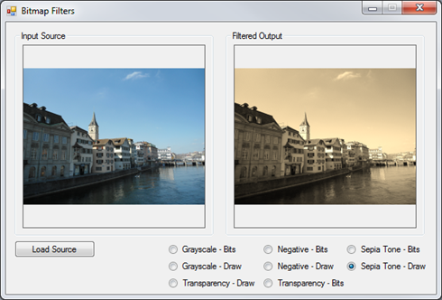
The filters described in this are all implemented by means of a . filtering is applied by selecting the corresponding radio button. The source loaded from the file system serves as input to the various filter methods, the filtered copy returned will be displayed next to the original source .

The following code snippet details the radio button checked changed event handler:

private void OnCheckChangedEventHandler(object sender, EventArgs e)
{
    if (picSource.BackgroundImage != null)
    {
        if (rdGrayscaleBits.Checked == true)
        {
             picOutput.BackgroundImage = picSource.BackgroundImage.CopyAsGrayscale();
        }
        else if (rdGrayscaleDraw.Checked == true)
        {
             picOutput.BackgroundImage = picSource.BackgroundImage.DrawAsGrayscale();
        }
        else if (rdTransparencyBits.Checked == true)
        {
             picOutput.BackgroundImage = picSource.BackgroundImage.CopyWithTransparency();
        }
        else if (rdTransparencyDraw.Checked == true)
        {
             picOutput.BackgroundImage = picSource.BackgroundImage.DrawWithTransparency();
        }
        else if (rdNegativeBits.Checked == true)
        {
             picOutput.BackgroundImage = picSource.BackgroundImage.CopyAsNegative();
        }
        else if (rdNegativeDraw.Checked == true)
        {
             picOutput.BackgroundImage = picSource.BackgroundImage.DrawAsNegative();
        }
        else if (rdSepiaBits.Checked == true)
        {
             picOutput.BackgroundImage = picSource.BackgroundImage.CopyAsSepiaTone();
        }
        else if (rdSepiaDraw.Checked == true)
        {
             picOutput.BackgroundImage = picSource.BackgroundImage.DrawAsSepiaTone();
        }
    }
}

Related Articles

C# How to: Drawing in GDI with Opacity/Alpha components

Article Purpose

In this article we explore GDI+ drawing operations implementing opacity, also known as alpha blending.

Sample source code

This article is accompanied by a sample source code Visual Studio project which is available for download here

C# How to: Drawing in GDI with Opacity/Alpha components

Using the Sample Application

The following is a screenshot of the included sample application:

GDIOpacityDrawing

The screenshot illustrates drawing text and a rectangle onto a Windows Form in Color.SteelBlue with an alpha component of 100.

GDI+ Drawing

In C# it is possible and relatively easy to draw text and two dimensional shapes in GDI+ that support a level of opacity or transparency. The well known abbreviation RGB abbreviates the term Red, Green and Blue. C# supports RGB colours but also what is known as ARGB colours. In the case of ARGB the A abbreviates the word Alpha, in other words an RGB colour with a specified alpha component.

An alpha component specifies a colour’s opacity or transparency. Possible values range from 0 to 255 inclusive, where 0 would represent full transparency and 255 no level of transparency. If a consists of 8 bits and an ARGB colour is composed of 4 components ranging from 0 to 255 each representing a or 8 bits, then an ARGB colour is therefore a 32 bit colour.

The Color structure

The System.Drawing namespace defines the Color structure, which exposes several functions aimed at creating an ARGB Color object instance:

The Paint Event Handler

The bulk of this example’s functionality occurs within the main Form’s handler, as detailed by the following code snippet:

private void MainFormPaintEventHandler(object sender, PaintEventArgs e) 
{ 
    Color alphaForeColor = Color.FromArgb(this.foreColorAlphaValue, this.ForeColor); 
    Pen rectanglePen = new Pen(alphaForeColor, 2.0f); 
    SolidBrush textBrush = new SolidBrush(alphaForeColor); 

float x = this.ClientRectangle.Width / 2.0f; x -= e.Graphics.MeasureString(textToDisplay, this .Font).Width / 2.0f;
float y = this.ClientRectangle.Height / 2.0f; y -= e.Graphics.MeasureString(textToDisplay, this.Font).Height / 2.0f;
e.Graphics.DrawString(textToDisplay, this.Font, textBrush, new PointF(x, y));
e.Graphics.DrawRectangle(rectanglePen, 25, 25, this.ClientRectangle.Width - 50, this.ClientRectangle.Height - 50); }

The main Form defines two member variables used in the handler:

 private byte foreColorAlphaValue = 100;
 textToDisplay = "http://softwarebydefault.com";

In the handler an instance of the structure is created implementing an alpha component defined by the ’s member variable. The object declaration is followed by an ARGB   Pen and SolidBrush declaration.

Next the code determines the X and Y coordinates that would result in drawing the ’s string member variable in the middle of the , after which the actual drawing occurs.

Using the Pen object declared earlier a rectangle is drawn 25 pixels inside the ’s ClientRectangle.


Dewald Esterhuizen

Blog Stats

  • 868,609 hits

Enter your email address to follow and receive notifications of new posts by email.

Join 228 other subscribers

Archives

RSS SoftwareByDefault on MSDN

  • An error has occurred; the feed is probably down. Try again later.